Methods and apparatus for driving electro-optic displays

a technology of electro-optic displays and apparatus, applied in the direction of electric digital data processing, instruments, computing, etc., can solve the problems of inadequate service life of electro-optic displays, preventing their widespread use, and gas-based electrophoretic media being susceptible to the same types of problems

Active Publication Date: 2005-12-22
E INK CORPORATION
View PDF99 Cites 209 Cited by
  • Summary
  • Abstract
  • Description
  • Claims
  • Application Information

AI Technical Summary

Benefits of technology

The present invention provides an improved method called the "dwell time compensation balanced pulse pair" (DTCBPP) method. This method has several technical benefits including being highly efficient and effective in achieving desired results. It also allows for easier implementation and use across various devices and platforms. Additionally, the DTCBPP method helps reduce the likelihood of errors and improve accuracy while maintaining high performance levels. Overall, the DTCBPP method offers better reliability and efficiency compared to existing techniques.

Problems solved by technology

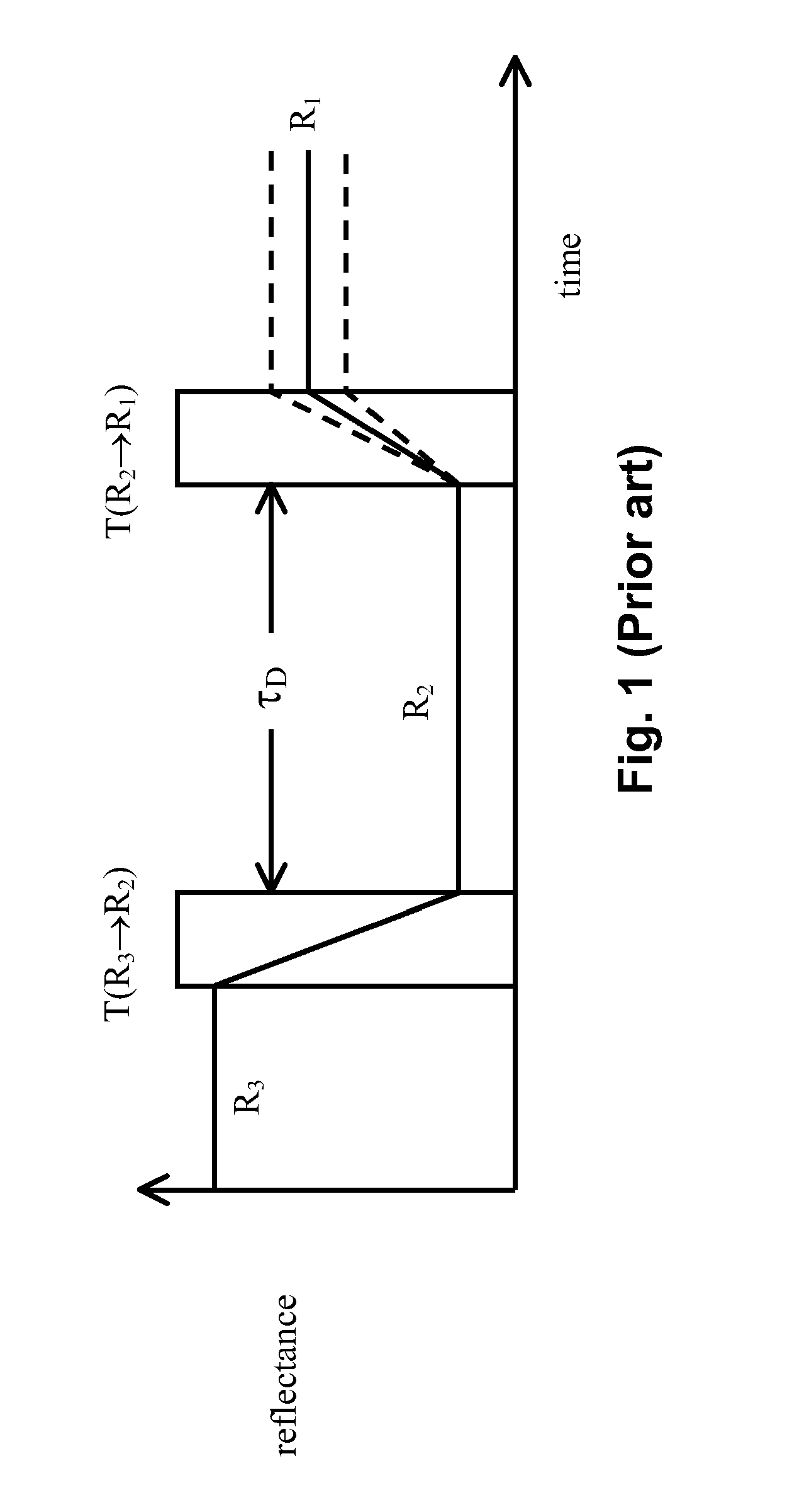
The technical problem addressed in this patent text includes how to compensate for differences in optical properties caused by aging of a display through repeated usage without introducing DC bias, and also how to improve the response time of the display by allowing faster updates during interaction with users. Additionally, the issue of unresponsive periods due to updated content needs to be solved to enable quicker interactions with users.

Method used


Image

  • Methods and apparatus for driving electro-optic displays
  • Methods and apparatus for driving electro-optic displays
  • Methods and apparatus for driving electro-optic displays

Examples


Embodiment Construction

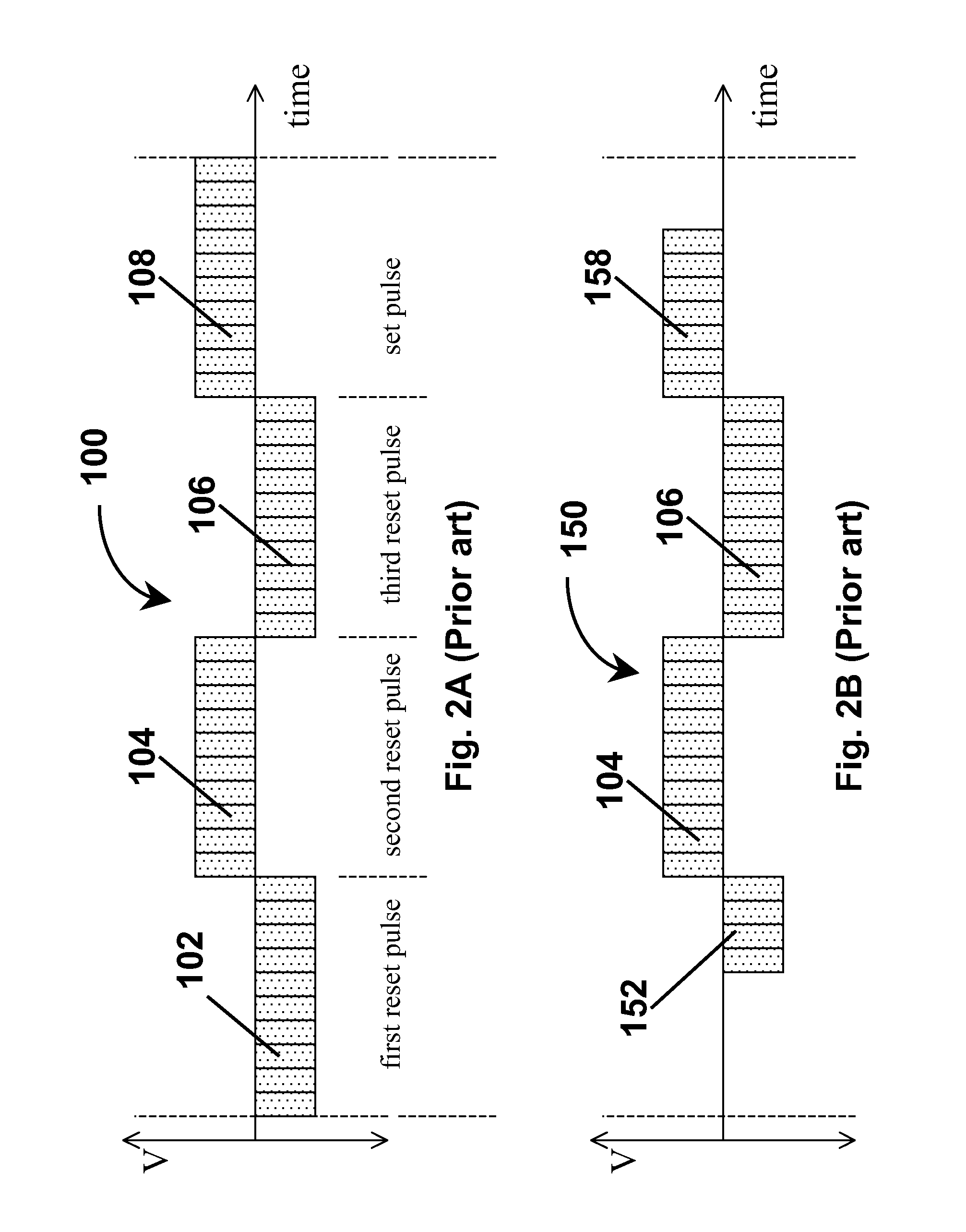
[0139] From the foregoing Summary, it will be seen that the present invention provides a number of differing methods for driving electro-optic displays, especially bistable electro-optic displays, and apparatus and software code adapted to carry out such methods. The various methods of the invention will mainly be described separately below, but it should be understood that a single electro-optic display, or component thereof, may make use of more than one aspect of the present invention. For example, a single electro-optic display might make use of the BPPSS, IMP and DTCBPP aspects of the present invention. It should also be noted that the preferred forms of balanced pulse pairs are common to all aspects of the present invention which make use of such pulse pairs, as are the preferred limitations on the sizes of such pulse pairs and the methods for adjusting the length of waveforms to accommodate insertion or excision of such pairs and / or periods of zero voltage. Finally, it should...


PUM


Abstract

Waveforms for driving electro-optic displays, especially bistable electro-optic displays, are modified by one or more of insertion of at least one balanced pulse pair into a base waveform; excision of at least one balanced pulse pair from the base waveform; and insertion of at least one period of zero voltage into the base waveform. Such modifications permit fine control of gray levels.

Description


Claims


Application Information

Patent Timeline
Owner E INK CORPORATION
Why Eureka
Try Eureka