Piercing unit, piercing member removal device, and piercing device

a technology for removing devices and piercing parts, which is applied in the field of piercing devices, piercing units, and piercing parts, and can solve problems such as troublesome user rotation operations

Inactive Publication Date: 2005-12-29
ARKRAY INC
View PDF6 Cites 95 Cited by
  • Summary
  • Abstract
  • Description
  • Claims
  • Application Information

AI Technical Summary

Benefits of technology

[0011] An object of the present invention is to provide a lancing unit, a lancing member removal tool and a lancing apparatus which are capable of solving or lessening the above-described problems.
[0018] Preferably, the support member includes a cap for covering the needle of the lancing member and removably supporting the lancing member.
[0031] According to a third aspect of the present invention, there is provided a lancing apparatus comprising a housing having a front end formed with an opening, a movable member arranged in the housing reciprocally movably and having a front end to which the lancing member can be fitted, biasing means for biasing the movable member toward the front end of the housing, latching means for latching the movable member when the movable member is pushed deep into the housing more than a predetermined distance against a biasing force of the biasing means, and latch releasing means for releasing the movable member from the latched state provided by the latching means when a predetermined operation is performed. The apparatus further comprises a stopper capable of preventing the movable member from being pushed deep into the housing more than the predetermined distance.

Problems solved by technology

However, the above prior art lancets have the following problems.
This rotation operation is troublesome for the user.

Method used


Image

  • Piercing unit, piercing member removal device, and piercing device
  • Piercing unit, piercing member removal device, and piercing device
  • Piercing unit, piercing member removal device, and piercing device

Examples


Embodiment Construction

[0062] Preferred embodiments of the present invention will be described below in detail with reference to the accompanying drawings.

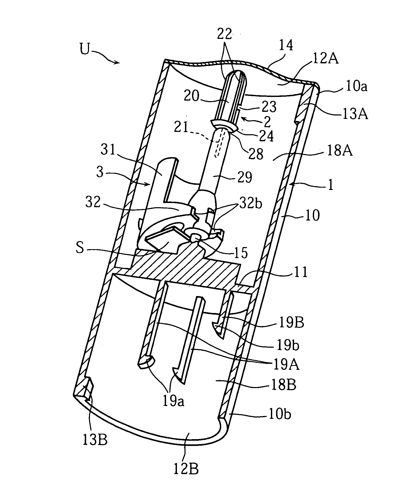
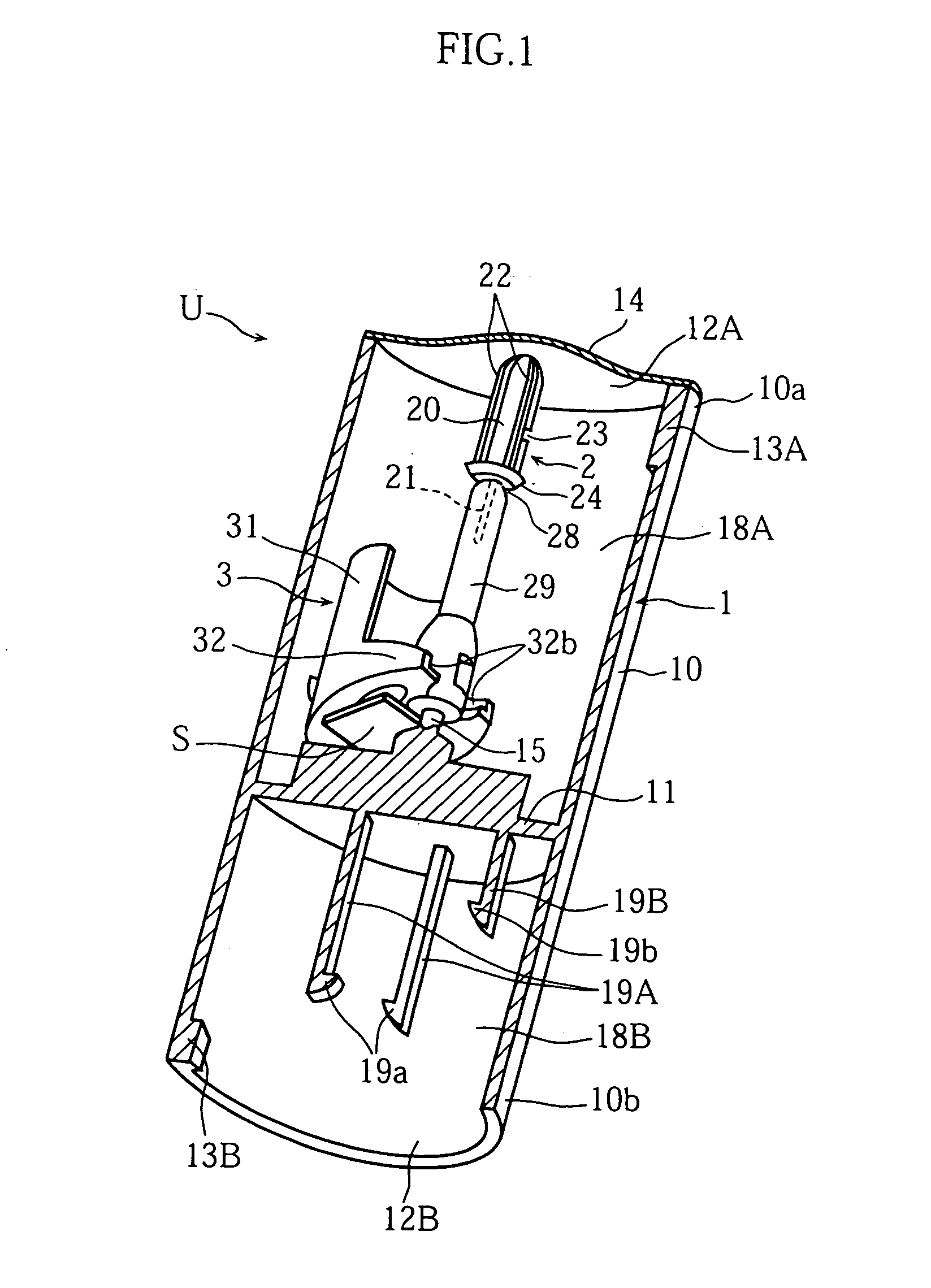
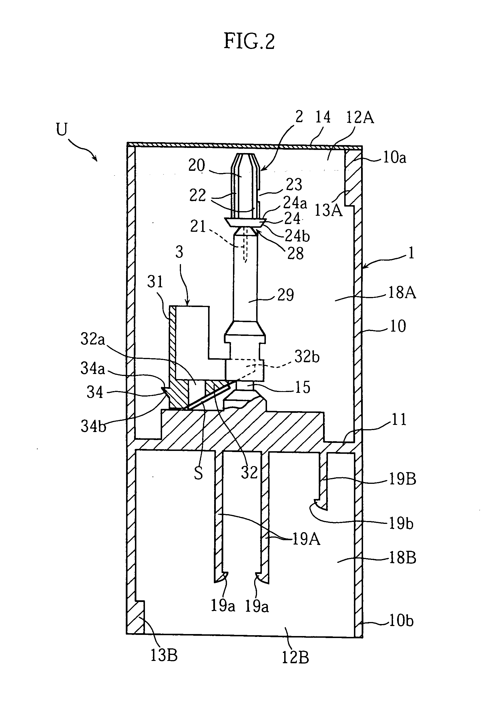
[0063]FIGS. 1-6 show an example of lancing unit according to the present invention.

[0064] As better shown in FIGS. 1 and 2, the lancing unit U of this embodiment includes a case 1, a lancet 2, a cap 29, a sensor holder 3, a pair of first engagement projections 19A and a second engagement projection 19B.

[0065] The case 1, which is made of e.g. synthetic resin, includes a generally cylindrical tubular portion 10 having a first end 10a and a second end 10b which are formed with openings 12A and 12B, respectively. The case further includes a partition wall 11 provided in the tubular portion 10. The partition wall 11 partitions the interior of the case 1 into a first and a second chambers 18A and 18B. The lancet 2, the cap 29 and the sensor holder 3 are arranged in the first chamber 18A. The paired first engagement projections 19A and the second engagemen...


PUM


Abstract

A lancing unit (U) includes a support member (1) provided with engagement means (19A) which is inserted into a housing (4) of a lancing apparatus (A) for engagement with an engagement surface (24a) of a lancing member (2) when the lancing member (2) is mounted to a movable member (5) of the lancing apparatus. The removal of the lancing member (2) from the movable member (5) after the lancing member (2) is mounted to the movable member (5) can be easily and reliably performed by inserting the engagement means (19A) into the housing (4) and then pulling the engagement means out of the housing (4).

Description

TECHNICAL FIELD [0001] The present invention relates to a lancing apparatus used to extract a sample such as blood, a lancing unit holding a disposable part as a unit and used as mounted to such a lancing apparatus, and a lancing member removal tool used for removing the lancing member mounted to a lancing apparatus. BACKGROUND ART [0002] Lancing apparatuses are often used for extracting blood of diabetics for measurement of the blood glucose levels. Generally, such a lancing apparatus includes a tubular housing having an open front end and a lancet holder arranged in the housing reciprocally movably. To use the lancing apparatus, a lancet of a disposable type is mounted to the lancet holder. Subsequently, with the front end of the housing held in contact with the skin of a human, the lancet and the lancet holder are advanced toward the front end of the housing so that the needle of the lancet lances the skin of the human. As a result, blood bleeds from the skin, whereby sampling of...

Claims


Application Information

Patent Timeline
Patent Type & Authority Applications(United States)
IPC IPC(8): A61B5/151A61B5/00A61B5/15
CPCA61B5/1411A61B5/15186A61B5/1486A61B5/150022A61B5/150099A61B5/150229A61B5/150358A61B5/150435A61B5/150549A61B5/150564A61B5/150572A61B5/150618A61B5/150717A61B5/150725A61B5/1509A61B5/150916A61B5/15113A61B5/15117A61B5/1519A61B5/15194A61B5/157
Inventor MATSUMOTO, DAISUKE
Owner ARKRAY INC
Why Eureka
Try Eureka