Weight Lifting And Selector Pin Assembly

a selector pin and weight lifting technology, applied in the direction of gymnastic exercise, muscle exercise devices, sport apparatus, etc., can solve the problems of not being movable, the selector pin is movable, so as to reduce the possibility of improper mating, and improve the selection of the desired weight to be lifted

Inactive Publication Date: 2017-09-14
BRONZE FIST DESIGN
View PDF0 Cites 15 Cited by
  • Summary
  • Abstract
  • Description
  • Claims
  • Application Information

AI Technical Summary

Benefits of technology

[0024]Thus, one object of the present invention is to provide a component for a weight lifting system which prevents the loss of a selector pin and the misuse of a weight training machine resulting from the loss thereof.
[0025]Another object of the present invention is to provide a selector pin and related car, ball or holder thereof which enables the continuous connection of the selector pin to a weight lifting device.
[0026]Still another object of the present invention is to provide a track or groove in a weight stack for a selector pin to enable the improved selection of a desired weight to be lifted.
[0027]Yet another object of the present invention is to provide a mechanism for the easy engagement of a selected weight level so as to reduce the possibility of an improper mating of the selector pin and the weight stack, thereby reducing the possibility of any in situ failure of the weight lifting machine.
[0028]Yet another object of the present invention is to provide a weight lifting machine that can eliminate the need for belts, pulleys or similar devices for transferring energy for the movement of a weight stack.

Problems solved by technology

A selector pin is movably mounted, but not removable from the movable car traveling within the horizontal internal cavity when the selector pin is disengaged from the selector stem within the radial extending cavity.
A selector pin is movably mounted, but not removable from the movable car traveling within the segmented track when the selector pin is disengaged from the selector stem within the radial extending cavity.

Method used


Image

  • Weight Lifting And Selector Pin Assembly
  • Weight Lifting And Selector Pin Assembly
  • Weight Lifting And Selector Pin Assembly

Examples


Embodiment Construction

[0062]Set forth below is a description of what is currently believed to be the preferred embodiment or best examples of the invention claimed. Future and present alternatives and modifications to this preferred embodiment are contemplated. Any alternatives or modifications which make insubstantial changes in function, in purpose, in structure or in result are intended to be covered by the claims in this patent.

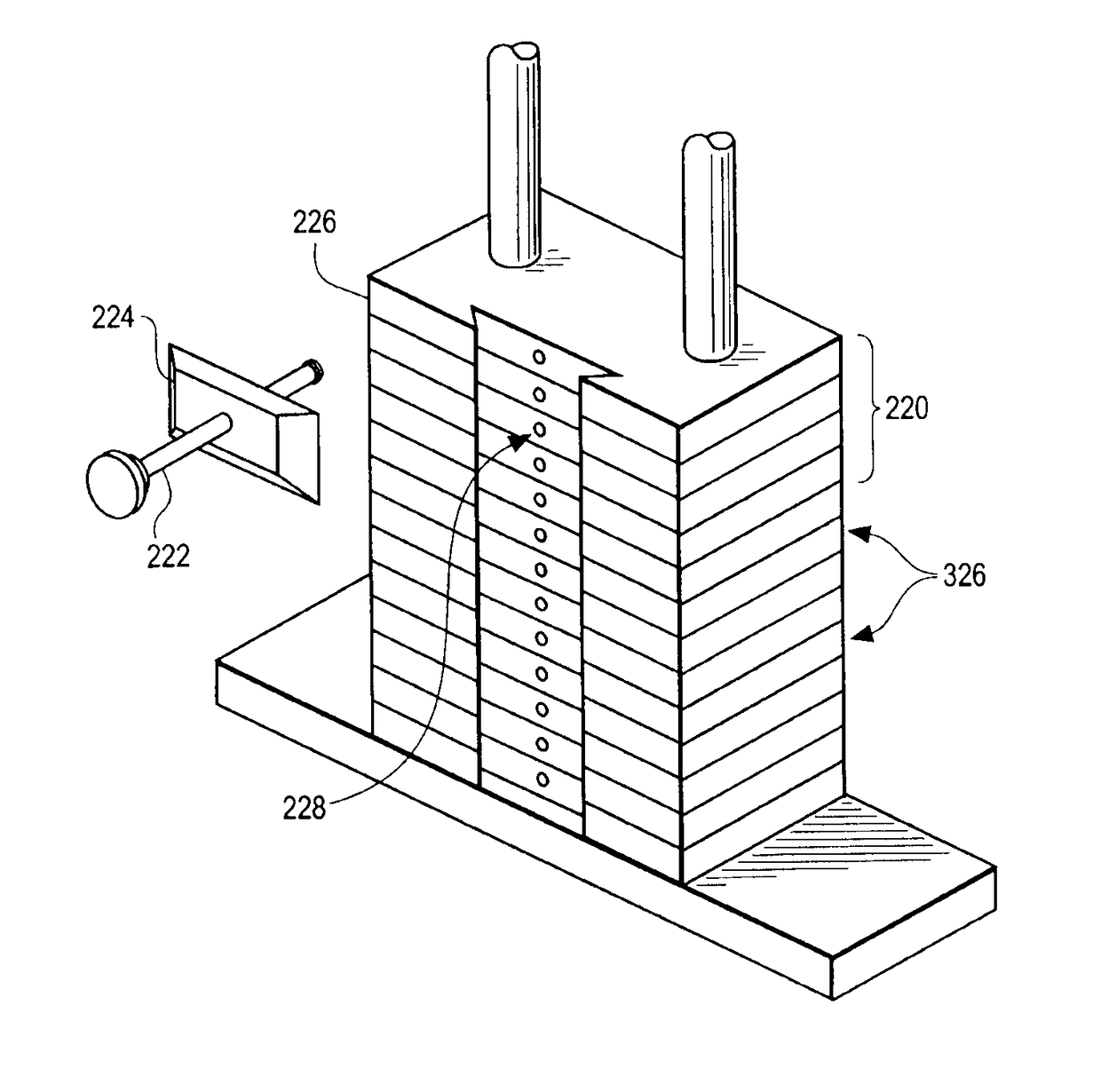
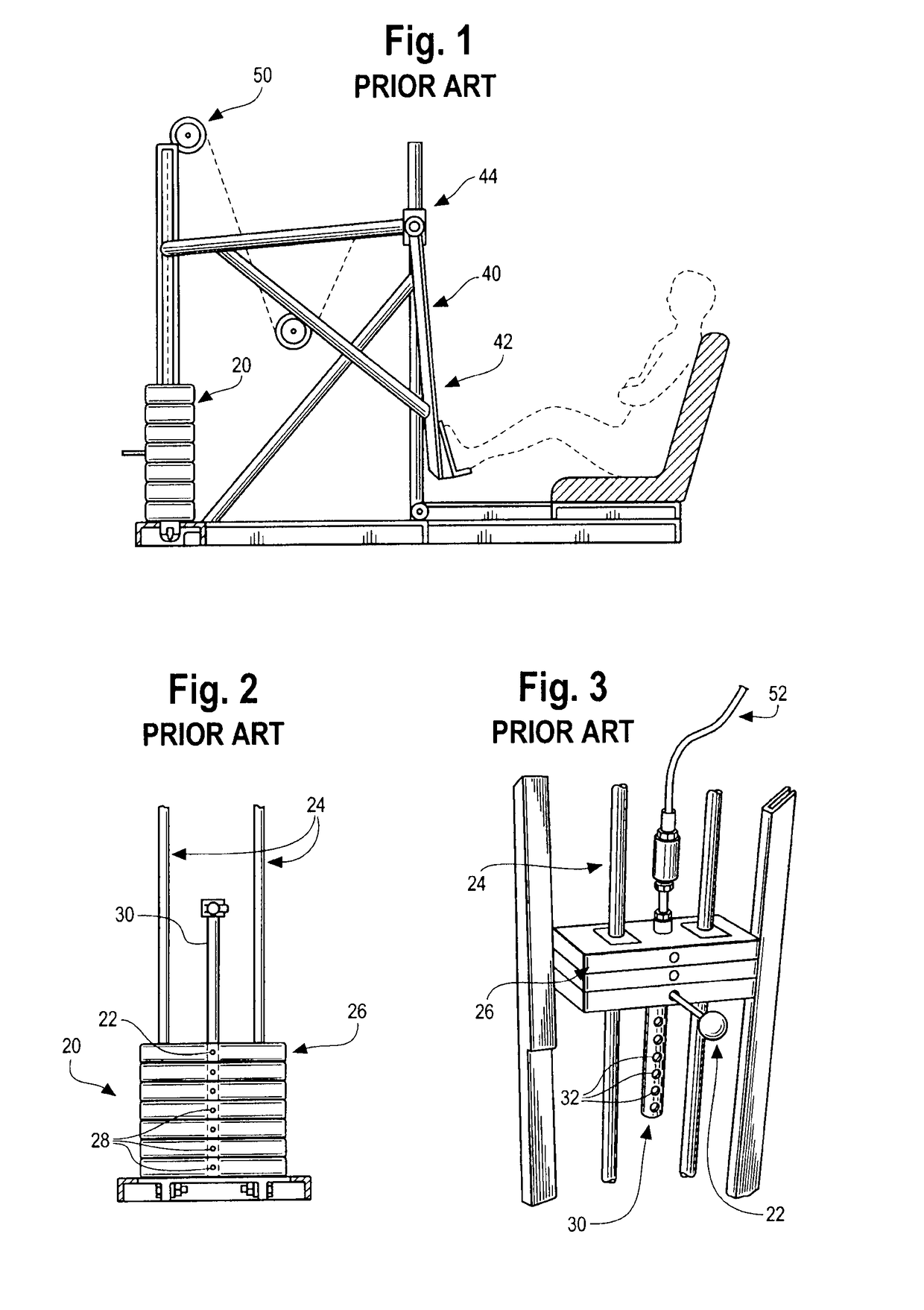
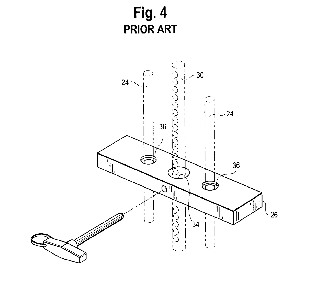
[0063]A typical weight lifting apparatus 10 as known in the prior art is shown by way of example in FIGS. 1-4. Generally, such an apparatus 10 includes a weight stack assembly 20, a movement assembly 40 for receiving work or force from a user, and a pulley system 50 to facilitate or translate the gravitational force from the weight stack assembly 20 so as to provide resistance to the movement assembly 40. The movement assembly 40 typically includes a movement arm 42 which is displaced by the user during exercise, and a pivot point 44 which permits rotation of the user's force ...


PUM


Abstract

A permanently affixed and travelling selector pin, car and weight plate selection mechanism for use with physical fitness equipment is disclosed including a segmented track and/or cut out cavern within the plate body for the car to travel within in either vertically or horizontally in order to select a different weight plate or cumulatively, more or less weight for an exercise. The selector pin and car mechanism features a selector pin which is not removable from the car and is inserted through the car which is contained by the track and or plate body shape and into a throughbore in the weight plate in order to engage with the selector stem.

Description

PRIORITY OF INVENTION[0001]The present invention is a continuation in part of patent application Ser. No. 14 / 076,461 filed Nov. 11, 2013, which is a continuation in part of patent application Ser. No. 13 / 653,852, filed Oct. 17, 2012. The present invention further incorporates by reference and claims priority to Provisional Application No. 61 / 629,443, Filed Nov. 18, 2011, Provisional Application No. 61 / 631,734, Filed Jan. 10, 2012, Provisional Application No. 61 / 824,189, Filed May 16, 2013.FIELD OF THE INVENTION[0002]The present invention relates to a weightlifting system and selector pin component thereof. In particular, this invention relates to a selector pin assembly, track and / or weight plate for use with body building equipment, and more particularly to a selector pin which is not removable from a car or ball which travels either along a track or within the weight plate bodies which can then be inserted through the car or ball and the track into a throughbore or selection point...

Claims


Application Information

Patent Timeline
Patent Type & Authority Applications(United States)
IPC IPC(8): A63B21/062
CPCA63B21/063A63B21/0632A63B21/0624A63B21/062A63B21/0615A63B23/03525A63B23/0429A63B2023/0452
Inventor SIMONETTI, DOMINIC A.
Owner BRONZE FIST DESIGN
Why Eureka
Try Eureka