In-situ corrosion controlling system for chemical vessels or tanks

Inactive Publication Date: 2006-01-05
UNITED MICROELECTRONICS CORP
View PDF11 Cites 6 Cited by
  • Summary
  • Abstract
  • Description
  • Claims
  • Application Information

AI Technical Summary

Benefits of technology

[0009] It is therefore the primary object of the present invention to provide an inexpensive, in-situ, continuous, real-time corrosion monitoring system

Problems solved by technology

The interior lining has potential of being attacked by the chemical liquid.

Method used


Image

  • In-situ corrosion controlling system for chemical vessels or tanks
  • In-situ corrosion controlling system for chemical vessels or tanks
  • In-situ corrosion controlling system for chemical vessels or tanks

Examples


Embodiment Construction

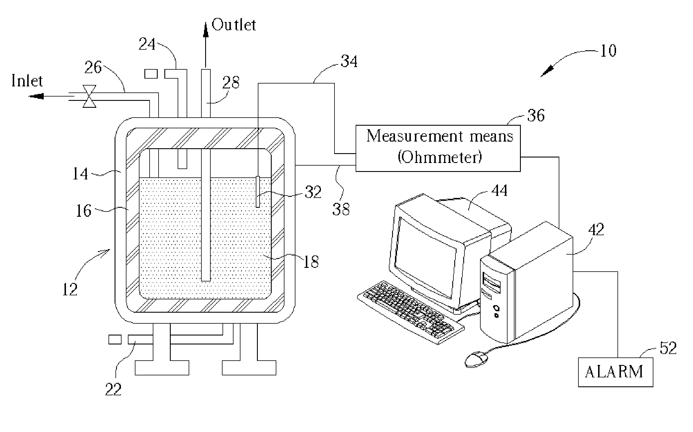
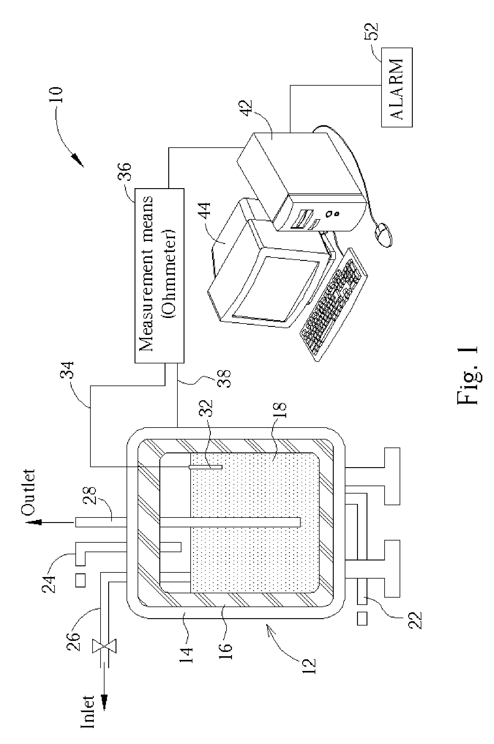
[0019] Please refer to FIG. 1. FIG. 1 is a schematic diagram illustrating a corrosion monitoring system 10 for chemical vessels or chemical tanks in accordance with one preferred embodiment of the present invention. Hereinafter, the term: “vessel” or “chemical vessel” refers to those containers including “tank”, “drum”, “tube”, “cylinder”, “reactor” or whatever employed to contain corrosive liquid chemicals either for storage / transportation purposes or for processing purposes. As shown in FIG. 1, the corrosion monitoring system 10 comprises a chemical vessel 12 comprising a conductive shell body 14 coated with an insulating interior lining 16. The chemical vessel 12 contains corrosive chemical liquid 18 in contact with the interior lining 16. The shell body 14 may be made of metal materials such as stainless steel, carbon steel, coated steel, aluminum or alloys.

[0020] It is to be understood that various types of piping or piping elements such as valves, gauges, or analytical instru...


PUM


Abstract

An in-situ and real-time corrosion controlling system for chemical vessels, tanks or reactors is disclosed. The chemical vessels, tanks or reactors are employed to contain high-purity corrosive chemicals such as acids, alkaline liquids or the like. The controlling system encompasses a vessel including a conductive shell and insulating interior lining coated therein. A robust detection electrode is dipped into the chemical liquid contained by the vessel. The detection electrode is electrically connected to a measurement means such as an ohmmeter that is mounted outside the vessel. The measurement means is further electrically connected to the conductive shell. When the interior lining is pitted due to the chemical attack by the chemical liquid and the chemical liquid contacts the conductive shell, the measurement means promptly receives a corresponding signal. According to one preferred embodiment, the measurement means is further connected to a controller unit that can control a semiconductor-processing unit.

Description

CROSS REFERENCE TO RELATED APPLICATIONS [0001] This is a continuation application of U.S. patent application Ser. No. 10 / 710,271 filed Jun. 30, 2004 by Lin et al.BACKGROUND OF INVENTION [0002] 1. Field of the Invention [0003] The present invention relates to a monitoring and controlling system for chemical vessels or tanks. More particularly, the present invention relates to an in-situ and real-time semiconductor process controlling system capable of effectively monitoring the integrity of an interior lining of chemical vessels and controlling the wet processing unit, thereby promoting quality and yield of the semiconductor process. [0004] 2. Description of the Prior Art [0005] Chemical supply system is essential to the semiconductor manufacturing. Typically, various processing chemicals are shipped from a dock or a chemical provider to a utility zone of a semiconductor factory by means of tank truck carriers. The tank truck carrier then discharges the liquidized processing chemical...

Claims


Application Information

Patent Timeline
IPC IPC(8): G01N27/26
CPCG01N27/205G01N17/00
Inventor LIN, HUNG-HSIANGLIN, KUN-YANGHONG, SHUN-LILEE, YUH-LANGSHEN, YU-ZEN
Owner UNITED MICROELECTRONICS CORP
Why Eureka
Try Eureka