Bone plate

a bone plate and plate body technology, applied in the field of bone plates, can solve the problems of high stress at the bone-screw and/or screw-plate interface, blade-shaped portion, and may require additional suppor

Active Publication Date: 2006-01-05
SYNTHES USA
View PDF99 Cites 122 Cited by
  • Summary
  • Abstract
  • Description
  • Claims
  • Application Information

AI Technical Summary

Benefits of technology

[0004] The present invention is directed to bone plate for fixation of a fractured bone. In one embodiment, the bone plate may comprise a first plate portion having a first longitudinal axis, an upper surface and a lower surface and a second plate portion having a second longitudinal axis, an upper surface and a lower surface. The second plate portion may be angled with respect to the first plate portion such that the lower surface of the first plate portion and the lower surface of the second plate portion define a first included angle therebetween. The first portion of the bone plate may have at least one hole for receiving a bone anchor having a shaft, the hole having a first hole portion defining a first central axis substantially perpendicular to the lower surface and a second hole portion overlapping and in communication with the first hole portion from upper to lower surface and defining a second central axis substantially angled with respect to the first central axis. The second hole portion of the bone plate may be configured to receive a bone anchor such that the shaft of the bone anchor is not substantially perpendicular with respect to the first portion of the bone plate. The second portion of the bone plate may be a blade having a proximal end adjacent the first portion of the bone plate and a distal end, the blade configured and adapted so that the distal end is inserted within the interior of the bone. The upper surface of the blade may include at least one channel. The blade may include a bore extending from its proximal end to its distal end, the bore being dimensioned and configured to receive a guide wire. The first included angle between the lower surface of the first portion and the lower surface of the second portion ranges from about 75° to about 150° and, more preferably about 75° to 110° or about 145° to about 120° depending upon the plates application.

Problems solved by technology

When treating certain types of fractures, such as that of the proximal portion of the femur, there may be high stresses at the bone-screw and / or screw-plate interfaces.
However these additional structures, for example the blade-shaped portion, may require additional support due to the redistribution of stresses from the loads experienced throughout the remainder of the bone plate.

Method used


Image

  • Bone plate
  • Bone plate
  • Bone plate

Examples


Embodiment Construction

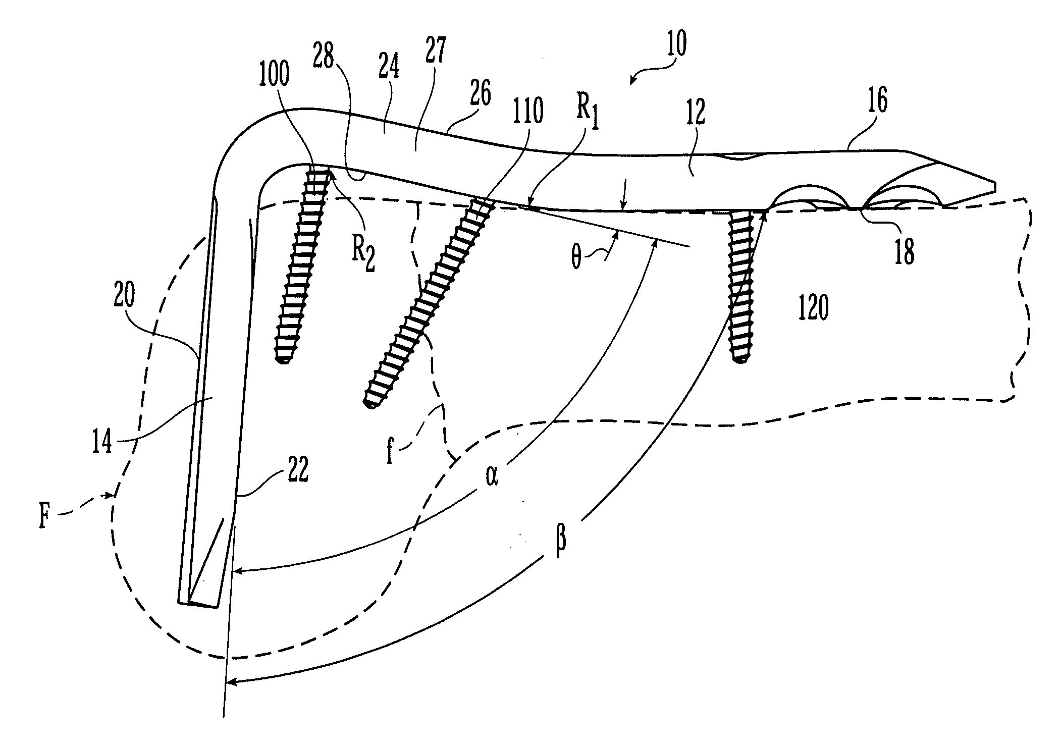
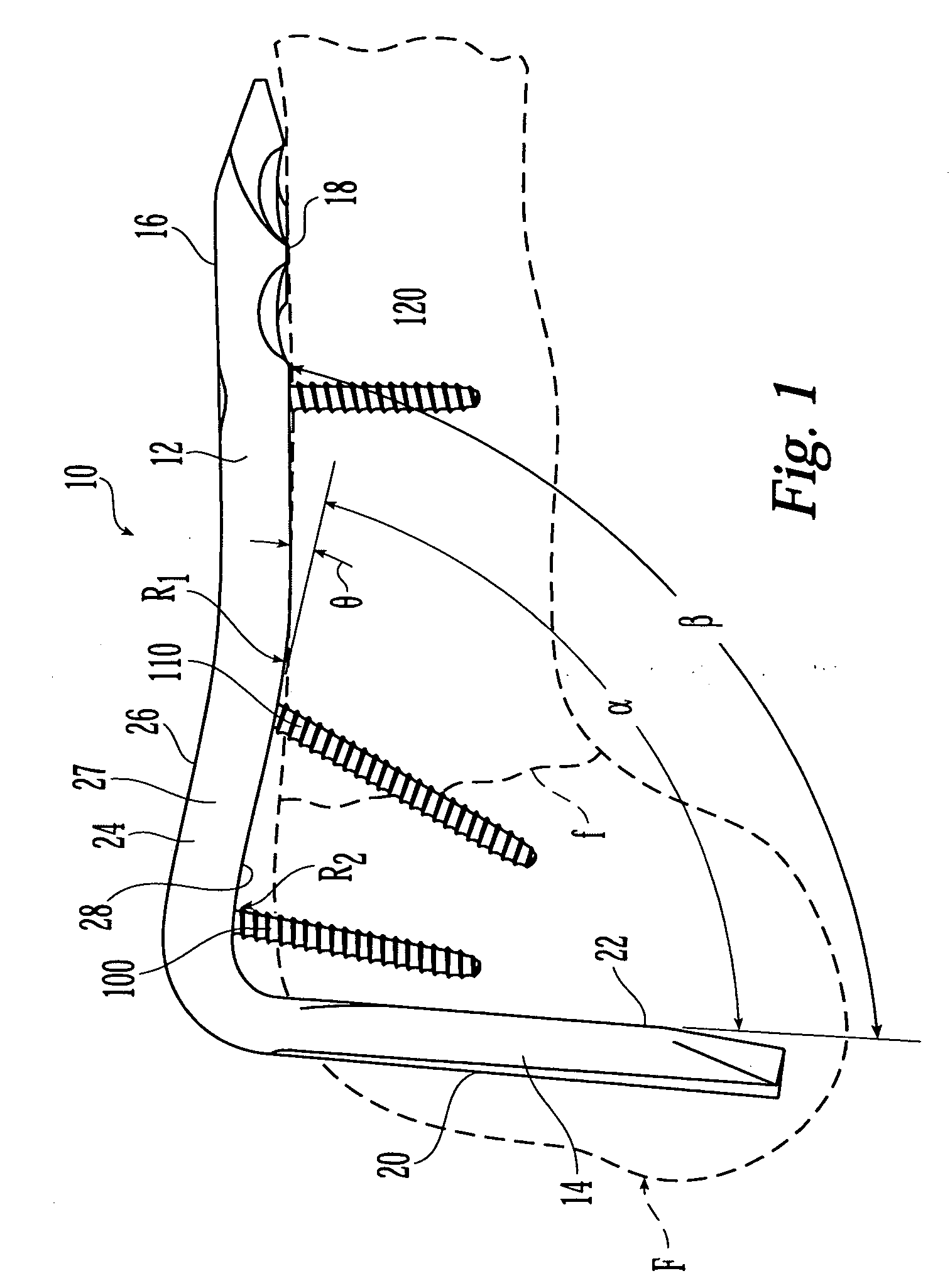
[0030] Shown in FIG. 1 is a first illustrative embodiment of bone plate 10 for use in internal fixation, compression and / or distraction of a bone, for example, the proximal portion of femur F, having a fracture f. One of ordinary skill in the art will know and appreciate, however, that the principles of the present invention may be applied to bone plates for fixation of other bones of humans and / or animals, such as, for example, long bones including the tibia, humerous, fibula, radius, ulna and for different parts or portions of long bones (e.g., the distal femur).

[0031] Bone plate 10 includes a first portion 12 that is configured to lie substantially parallel to the surface of bone F anchored by a plurality of bone anchors 100, 110, 120. Preferably, first portion 12 is substantially elongated and, preferably, substantially straight, as illustrated in FIG. 1. The elongated plate portion 12 includes an upper surface 16 and a lower or bone surface 18. The bottom or lower surface 18 m...


PUM


Abstract

A bone plate for fixation of a fractured bone comprises a first portion having a first longitudinal axis, an upper surface and a lower surface and a second portion having a second longitudinal axis, an upper surface and a lower surface. The second portion is angled with respect to the first portion such that the lower surface of the first portion and the lower surface of the second portion define an included angle therebetween. The first portion has at least one hole for receiving a bone anchor having a shaft. The hole has a first hole portion defining a first central axis substantially perpendicular to the lower surface and the first hole portion is configured to receive the bone anchor. The hole includes a second hole portion overlapping and in communication with the first hole portion from upper to lower surface defining a second central axis substantially angled with respect to the first central axis, the second hole portion is configured to receive the bone anchor such that the shaft is substantially angled with respect to the second portion of the bone plate so as to form a truss.

Description

FIELD OF THE INVENTION [0001] The present invention relates generally to bone plates, and more specifically, to bone plates having a blade portion for the fixation of fractured bone, preferably long bones, including the femur and the tibia. BACKGROUND OF THE INVENTION [0002] A bone plate is a plate that is fastenable to the surface of a fractured bone to support and / or stabilize the fracture as the bone heals. Bone plates may be attached to the bone with bone screws that extend from the plate into the bone. In some examples, the head of the bone screw is locked to the plate (e.g., by threaded engagement between the screw head and the bone plate) and in other plates the head of the screw is free to angulate with respect to the plate, such that the screw may be placed in the bone at a surgeon-selected angle. In yet other examples, the screw head may cooperate with the bone plate to provide compression or distraction of the fracture (i.e., to push the bone fragments towards or away fro...

Claims


Application Information

Patent Timeline
Patent Type & Authority Applications(United States)
IPC IPC(8): A61B17/56
CPCA61B17/74A61B17/809A61B17/8057A61B17/8014A61B17/58
Inventor HAYECK, GARRYHAAG, RENEKIM, HENRYGRADY, MARK P. JR.
Owner SYNTHES USA
Why Eureka
Try Eureka