Bone plate

a bone plate and plate body technology, applied in the field of bone plates, can solve the problems of high stress at the bone-screw and/or screw-plate interface, large amount of bone to be removed, and difficulty in surgical procedures, so as to reduce the gap of bone fractures and reduce bone fractures

Active Publication Date: 2011-05-31
SYNTHES USA
View PDF314 Cites 129 Cited by
  • Summary
  • Abstract
  • Description
  • Claims
  • Application Information

AI Technical Summary

Benefits of technology

[0010]The present invention is also generally directed to a method of using a bone plate according to the present invention for reducing bone fractures. The method comprises the steps of affixing an embodiment of a bone plate according to the present invention across the gap of a fracture zone and engaging the threaded head of a bone screw in a threaded hole of the bone plate so as form a threaded locked engagement. The threaded hole is configured for threaded locked engagement with the threaded head of the bone screw. The threaded hole may fix the bone screw along an axis at such an angle relative to the lower surface of the bone plate such that upon the threaded locked engagement of the bone screw with the bone plate, the gap of the bone fracture is reduced.

Problems solved by technology

When treating certain types of fractures, such as that of the proximal portion of the femur, there may be high stresses at the bone-screw and / or screw-plate interfaces.
With both of these systems, however, a large amount of bone must be removed to accommodate the blade or barrel.
In addition, the surgical procedures are technically difficult, as the bone must be removed with precision in order to allow proper positioning of the bone plate on the bone.

Method used


Image

  • Bone plate
  • Bone plate
  • Bone plate

Examples


Embodiment Construction

[0041]For convenience, the same or equivalent elements in various embodiments of the bone plate illustrated in the drawings have been identified with the same reference numerals. Further, in the description that follows, any reference to either orientation or direction is intended primarily for the convenience of description and is not intended in any way to limit the scope of the present invention thereto.

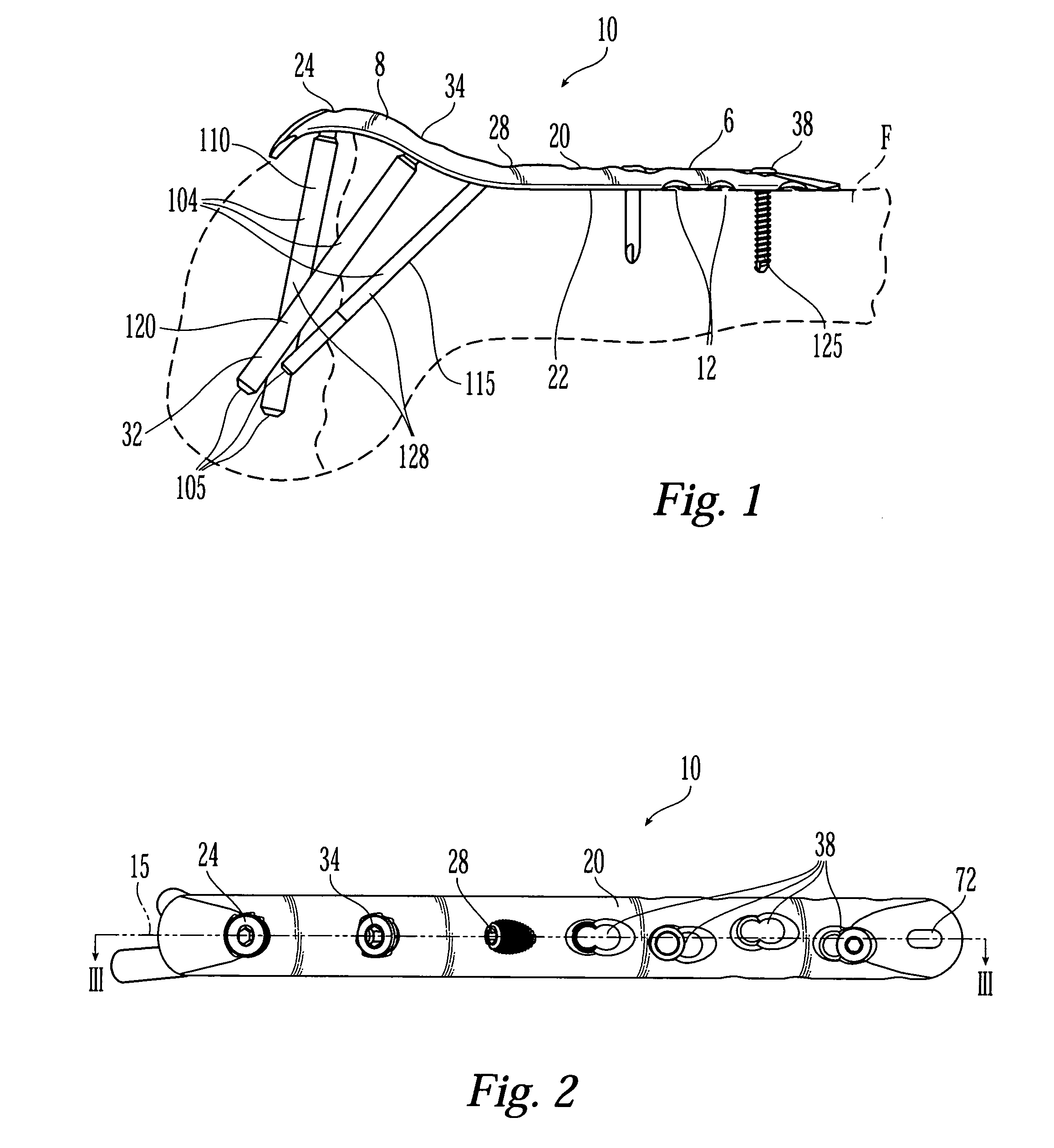
[0042]A first illustrative embodiment of a bone plate 10 is shown in FIG. 1. The bone plate 10 shown in FIG. 1 is dimensioned and configured for internal fixation of the proximal portion of a fractured femur F. One of ordinary skill in the art will know and appreciate, however, that the principles of the present invention may be applied to bone plates for fixation of other bones of humans and / or animals, for example long bones, and for different parts of long bones (e.g., the proximal tibia, the distal femur, etc.).

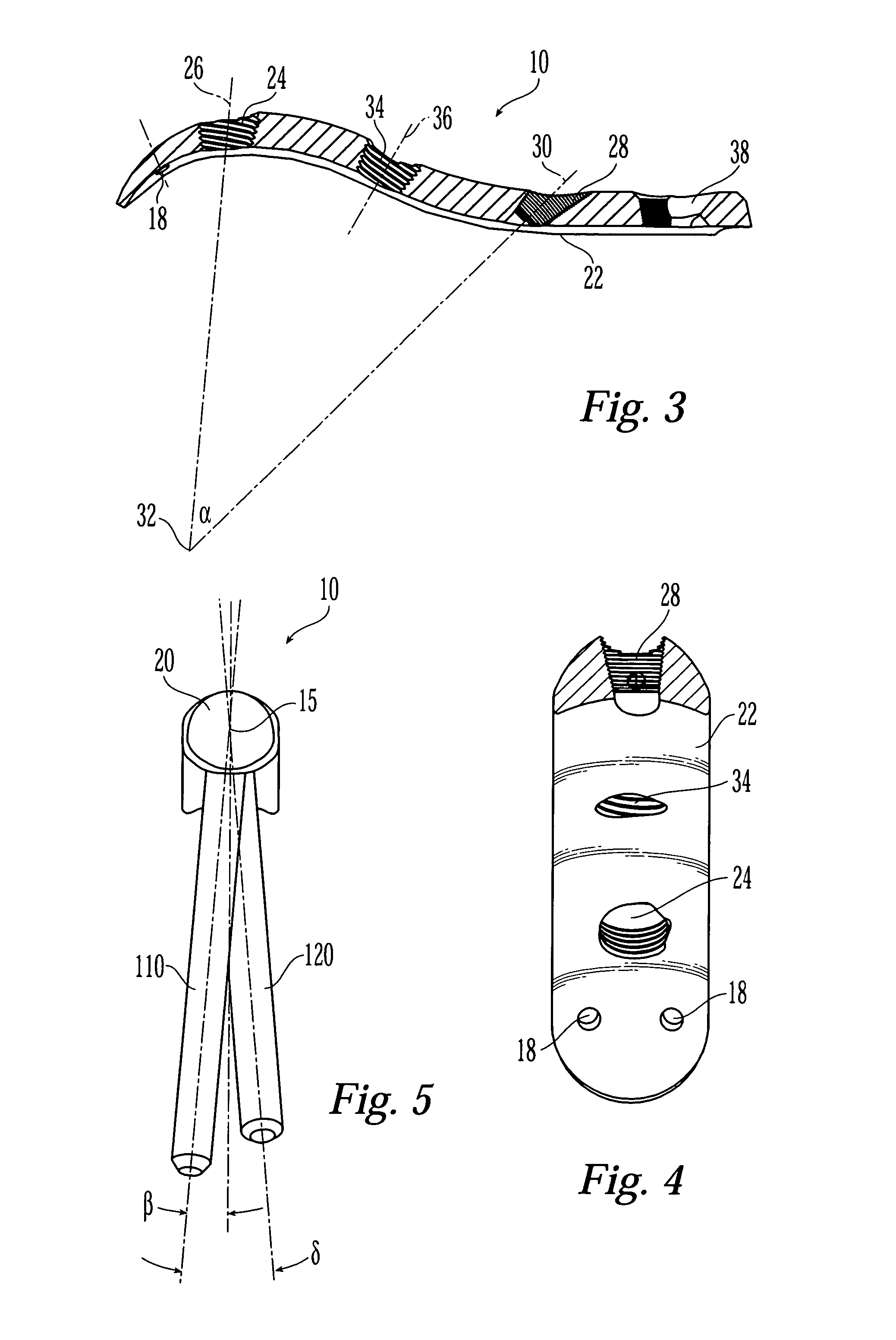
[0043]As shown in FIGS. 1 and 2, bone plate 10 has a longitudinal ...


PUM


Abstract

The present invention is directed to a bone plate and its method of use for reducing a bone fracture, the bone plate having a longitudinal axis, the bone plate comprising an upper surface, a lower surface, a first hole for engaging a head of a first bone anchor. The first hole is configured and adapted to fix a shaft of the first bone anchor along a first axis. A second hole is spaced apart from the first hole along the longitudinal axis. The second hole is for engaging a head of a second bone anchor, and is configured and adapted to fix a shaft of the second bone anchor along a second axis. The first hole and the second hole are configured such that the first axis and the second axis define a single plane and intersect at a point below the lower surface. The shafts of the first and second bone anchors may touch or nearly touch at the point of intersection, such that the first and second bone anchors form a truss.

Description

TECHNICAL FIELD OF THE INVENTION[0001]The present invention relates generally to bone plates, and more specifically, to bone plates for the fixation of parts of a fractured bone, preferably long bones, including the femur and the tibia.BACKGROUND OF THE INVENTION[0002]A bone plate is a plate that is fastenable to the surface of a bone typically at both sides of a fracture to support and / or stabilize the fracture. Bone plates have typically been attached to the bone with bone screws that extend from the plate into the bone. In some examples, the head of the bone screw is locked to the plate (e.g., by threaded engagement between the screw head and the bone plate) and in other plates the head of the screw is free to angulate with respect to the plate, such that the screw may be placed in the bone at a surgeon-selected angle. In yet other examples, the screw head may cooperate with the bone plate to provide compression or distraction of the fracture (i.e., to push the bone fragments tow...

Claims


Application Information

Patent Timeline
Patent Type & Authority Patents(United States)
IPC IPC(8): A61B17/80A61BA61B17/56A61B17/86
CPCA61B17/746A61B17/8052A61B17/74A61B17/809A61B17/8014A61B17/8066A61B17/86A61B17/8057A61B17/58A61B17/56A61B17/80
Inventor GRADY, JR., MARK P.HAAG, RENEDIDOMENICO, SCOTTKOAY, KENNYMAST, JEFF W.BOLHOFNER, BRETT RMAYO, KEITH A.
Owner SYNTHES USA
Why Eureka
Try Eureka