Methods for reducing bone compression fractures using wedges

a technology of compression fractures and wedges, applied in the field of bone structure treatment, can solve the problems of limited distance movement of wedge-shaped devices relative to other wedge-shaped devices, and achieve the effect of reducing bone fractures and reducing compression fractures within the bone structur

Active Publication Date: 2007-08-07
BOSTON SCI SCIMED INC
View PDF30 Cites 34 Cited by
  • Summary
  • Abstract
  • Description
  • Claims
  • Application Information

AI Technical Summary

Benefits of technology

[0006]To this end, the rigid body has a leading side, a lagging side opposite the leading side, and a tapered side between the leading and lagging sides. In the preferred embodiment, the tapered and leading sides form a point so that, e.g., the wedge-shaped device can be easily inserted between two other wedge-shaped devices. In the preferred embodiment, the leading and lagging sides are also substantially parallel to each other to, e.g., facilitate stacking of wedge-shaped devices on top of each other. The rigid body may also comprise a driven side between the leading and lagging sides opposite the tapered side. A notch can be formed between the leading and driven sides, so that, e.g., a pair of the wedge-shaped devices, when placed back-to-back (i.e., with their leading edges engaging each other) can be more easily be split apart by another wedge pair, thereby facilitating stacking of the wedges. The rigid body may also comprise another notch formed along the leading side that complements the lagging side. In this case, distal movement of a wedge-shaped device relative to another wedge-shaped device can be limited when the lagging edge of one wedge is slid within the notch of the leading edge of another wedge.
[0008]The kit may also comprise another plurality of wedges, each having substantially parallel opposing sides, a blunted side between the opposing sides, and a driven side between the opposing sides and opposite the blunted side. The blunted side of these wedges reduces the risk of injuring the distal side of the bone structure. The kit may include an optional plunger assembly configured to be introduced within the cannula lumen. As an example, the plunger assembly can be used to convey treatment media, e.g., bone cement, through the cannula lumen into the bone structure.
[0011]In accordance with a fourth aspect of the present inventions, a wedge-shaped device for reducing a bone fracture (e.g., a vertebral compression fracture) is provided. The wedge-shaped device comprises a biocompatible body having a leading side, a lagging side opposite the leading side, and a tapered side between the leading and lagging sides. The wedge-shaped device additionally comprises a longitudinal bore that extends through the biocompatible body, e.g., from the driven side to the tapered side of the body. Although the present invention should not be so limited in its broadest aspects, the longitudinal bore allows the wedge-shaped device to be introduced over a guide member into a bone cavity. The cross-sectional shape of the bore can be any suitable shape, but in the preferred embodiment, is non-circular (e.g., oval). In this manner, the wedge-shaped device can be more easily rotationally aligned with respect to the guide member.
[0012]In accordance with a fifth aspect of the present inventions, a kit for reducing a bone fracture (e.g., a vertebral compression fracture) is provided. The kit comprises a plurality of biocompatible wedges, each of which has a bore extending therethrough, and a guide member sized to fit through the bore. Although the present invention should not be so limited in its broadest aspects, the use of a guide member, as opposed to a cannula, minimizes the size of the access passage through which the guide member can be introduced into the bone structure, thereby minimizing the trauma caused to the bone structure. Alternatively, the size of the wedges can be maximized without increasing the size of the access passage.
[0014]In accordance with a sixth aspect of the present inventions, a method of treating a bone structure having a compression fracture (e.g., a vertebral compression fracture) is provided. The method comprises introducing a guide member into the bone structure, and introducing wedges over the guide member in a direction lateral to the compression fracture, e.g., by pushing the wedges with a wedge driver that is itself introduced over the guide member. The wedges are introduced into the bone structure, such that a subsequently introduced wedge is placed in contact with a previously introduced wedge. As a result, previously introduced wedges are displaced in a direction towards one or both of the opposing sides of the bone structure. Because a guide member is used to introduce the wedges into the bone structure, any access passage made in the bone structure can be minimized, or alternatively, the size of the wedges can be maximized. The method may optionally include introducing treatment media into the bone structure after introduction of the wedges.

Problems solved by technology

In this case, distal movement of a wedge-shaped device relative to another wedge-shaped device can be limited when the lagging edge of one wedge is slid within the notch of the leading edge of another wedge.

Method used


Image

  • Methods for reducing bone compression fractures using wedges
  • Methods for reducing bone compression fractures using wedges
  • Methods for reducing bone compression fractures using wedges

Examples


Embodiment Construction

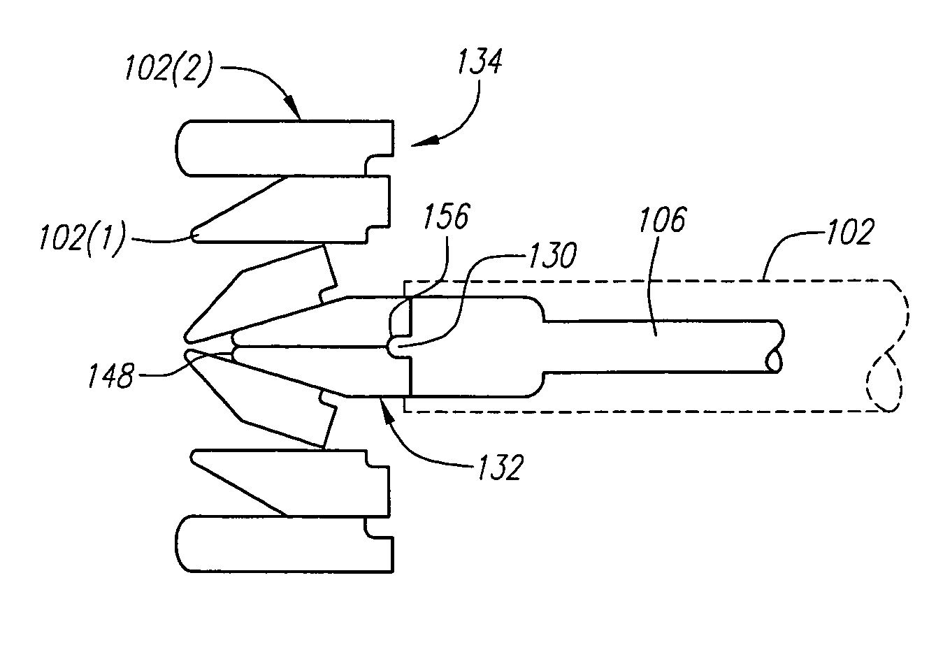
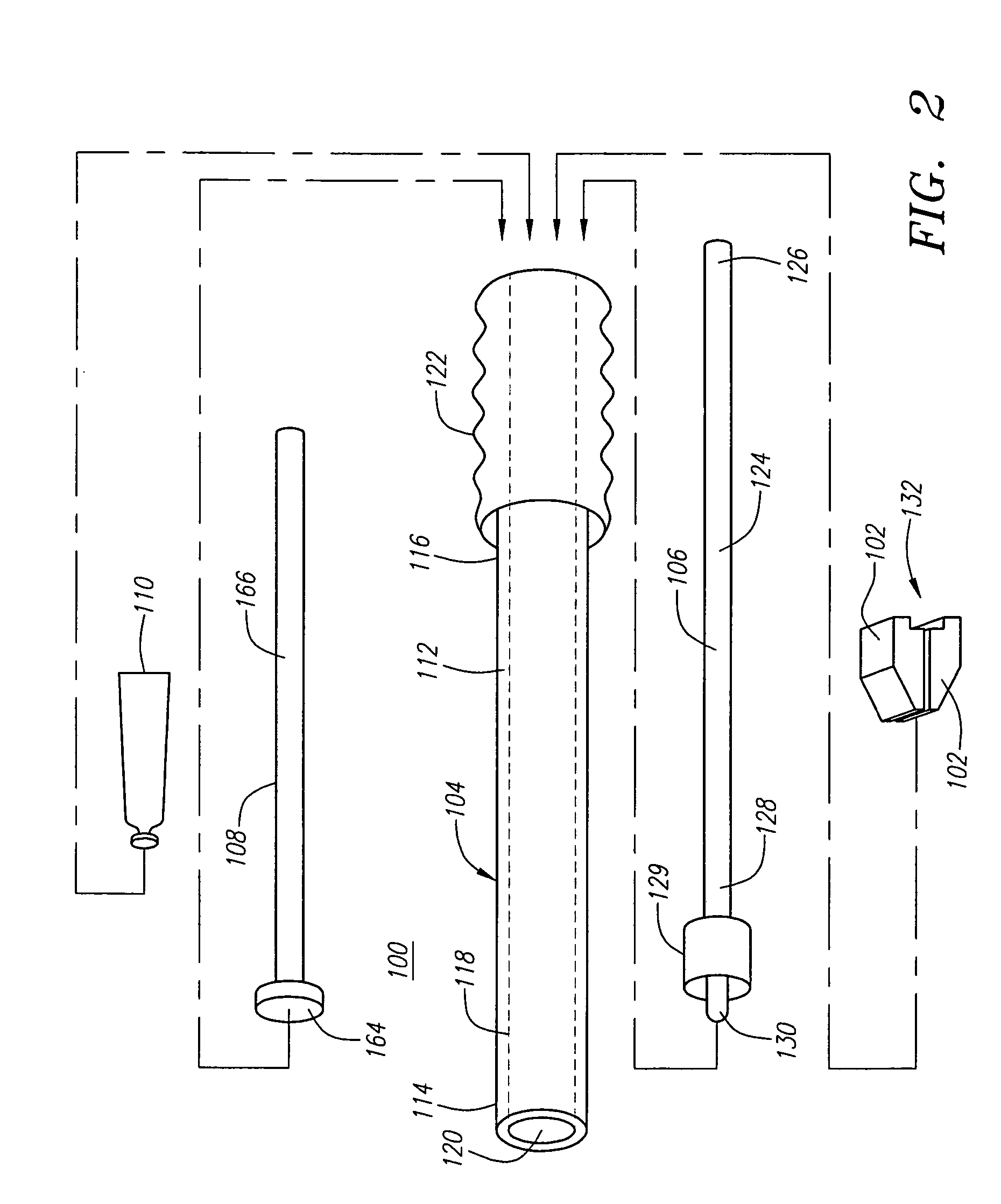
[0039]Referring to FIG. 2, a bone fracture treatment kit 100 constructed in accordance with one preferred embodiment of the present inventions is illustrated. The kit 100 can be used for treating a bone compression fracture, and specifically, a compression fracture 202 within a vertebra 200 (shown in FIGS. 13-18). The kit 100 generally comprises a plurality of fracture reducing wedges 102 (shown in FIG. 2 as a pair of wedges 102), a delivery member, and specifically a cannula 104, for delivery of therapeutic agents (e.g., the wedges 102 and a therapeutic medium) into the vertebra 200, a wedge driver 106 for pushing the wedges 102 through the cannula 104 into the vertebra 200 in order to reduce the compression fracture 202, and an optional plunger assembly 108 for forcing a therapeutic medium 110 through the cannula 104 and into the vertebra 200 in order to stabilize and set the vertebra 200.

[0040]Referring still to FIG. 2, the cannula 104 comprises a shaft 112 having a distal end 11...


PUM


Abstract

Devices, kits, and methods are provided for treating a bone structure, e.g., a vertebra, with a compression fracture. Wedges can be introduced into the bone structure in a direction that is lateral to the compression fracture, and stacked on tope of each to apply forces to the bone structure to reduce the compression fracture. The wedges can be introduced into the bone structure using a cannula. The wedges can be introduced as wedge pairs, in which case, a subsequent wedge pair can be introduced between a previously introduced wedge pair in order to drive the previously introduced wedges apart to create the stacking arrangement. Optionally, the wedges can be provided with longitudinal bores, in which case, they can be introduced into the bone structure, over a guide member that is threaded through the bores.

Description

FIELD OF THE INVENTION[0001]The invention relates to the treatment of bone structures, such as vertebrae, and in particular, to the reduction and stabilization of bone compression fractures.BACKGROUND OF THE INVENTION[0002]Spinal injuries, bone diseases, such as osteoporosis, vertebral hemangiomas, multiple myeloma, necrotic lesions (Kummel's Disease, Avascular Necrosis), and metastatic disease, or other conditions can cause painful collapse of vertebral bodies. Osteoporosis is a systemic, progressive and chronic disease that is usually characterized by low bone mineral density, deterioration of bony architecture, and reduced overall bone strength. Vertebral compression fractures (VCF) are common in patients who suffer from these medical conditions, often resulting in pain, compromises to activities of daily living, and even prolonged disability.[0003]FIG. 1 illustrates three vertebrae 10, 12, and 14, each with an anterior side 16, a posterior side 18, and lateral sides 20 (only one...

Claims


Application Information

Patent Timeline
Patent Type & Authority Patents(United States)
IPC IPC(8): A61F2/44A61B17/00A61B17/34A61B17/88
CPCA61B17/3468A61B17/8852A61B17/3472A61B2017/00261
Inventor CARRISON, HAROLD F.OLSON, JR., STANLEY W.JANSEN, LEX P.
Owner BOSTON SCI SCIMED INC
Why Eureka
Try Eureka