Optical circuit having legs in a stacked configuration and an associated fabrication method

a technology of optical circuits and legs, applied in the direction of bundled fibre light guides, instruments, fibre mechanical structures, etc., can solve the problems of reducing the performance of flexible optical circuits, introducing attenuation and other deleterious effects, and increasing the length of optical fiber ribbons is oftentimes disadvantageous for fiber management, so as to reduce the stress to which optical fibers are subjected, and achieve the effect of eliminating the stress of optical fibers, without degrading the performance of flexibl

Inactive Publication Date: 2005-02-01
US CONEC
View PDF2 Cites 49 Cited by
  • Summary
  • Abstract
  • Description
  • Claims
  • Application Information

AI Technical Summary

Benefits of technology

An improved optical circuit is therefore provided having a plurality of legs, each of which may have one or more optical fibers bound together by a matrix material, arranged in a stacked configuration in such a manner as to reduce, if not eliminate, the stress to which the optical fibers are subjected. As such, a fiber optic connector may be mounted upon the legs in the stacked configuration without degrading the performance of the optical circuit, i.e., without disadvantageously increasing the attenuation of the optical signals transmitted thereby. By facilitating the arrangement of the legs in a stacked configuration, the optical circuit of the present invention permits the legs to have relatively short lengths which, in turn, improves the fiber management and organization of the optical circuit. Moreover, the optical circuit of the present invention may advantageously permit the size of the main body to be reduced since the optical fibers need not be spread as widely as in conventional optical circuits. Additionally, an advantageous method for manufacturing an optical circuit having a plurality of legs arranged in a stacked configuration is also provided.

Problems solved by technology

As known to those skilled in the art, stress is disadvantageous for optical fibers and may introduce attenuation and have other deleterious performance effects.
While the lengthening of the ribbons of optical fibers reduces, to some extent, the stress to which the optical fibers are subjected, the increased length of the ribbons of optical fibers is oftentimes disadvantageous for fiber management and organization purposes.
Moreover, while the stress to which the optical fibers is subjected may be reduced somewhat by increases in the length of the ribbons of optical fibers, the optical fibers will still be subjected to at least some stress which, in turn, degrades the performance of the flexible optical circuit.

Method used


Image

  • Optical circuit having legs in a stacked configuration and an associated fabrication method
  • Optical circuit having legs in a stacked configuration and an associated fabrication method
  • Optical circuit having legs in a stacked configuration and an associated fabrication method

Examples


Embodiment Construction

The present invention now will be described more fully hereinafter with reference to the accompanying drawings, in which preferred embodiments of the invention are shown. This invention may, however, be embodied in many different forms and should not be construed as limited to the embodiments set forth herein; rather, these embodiments are provided so that this disclosure will be thorough and complete, and will fully convey the scope of the invention to those skilled in the art. Like numbers refer to like elements throughout.

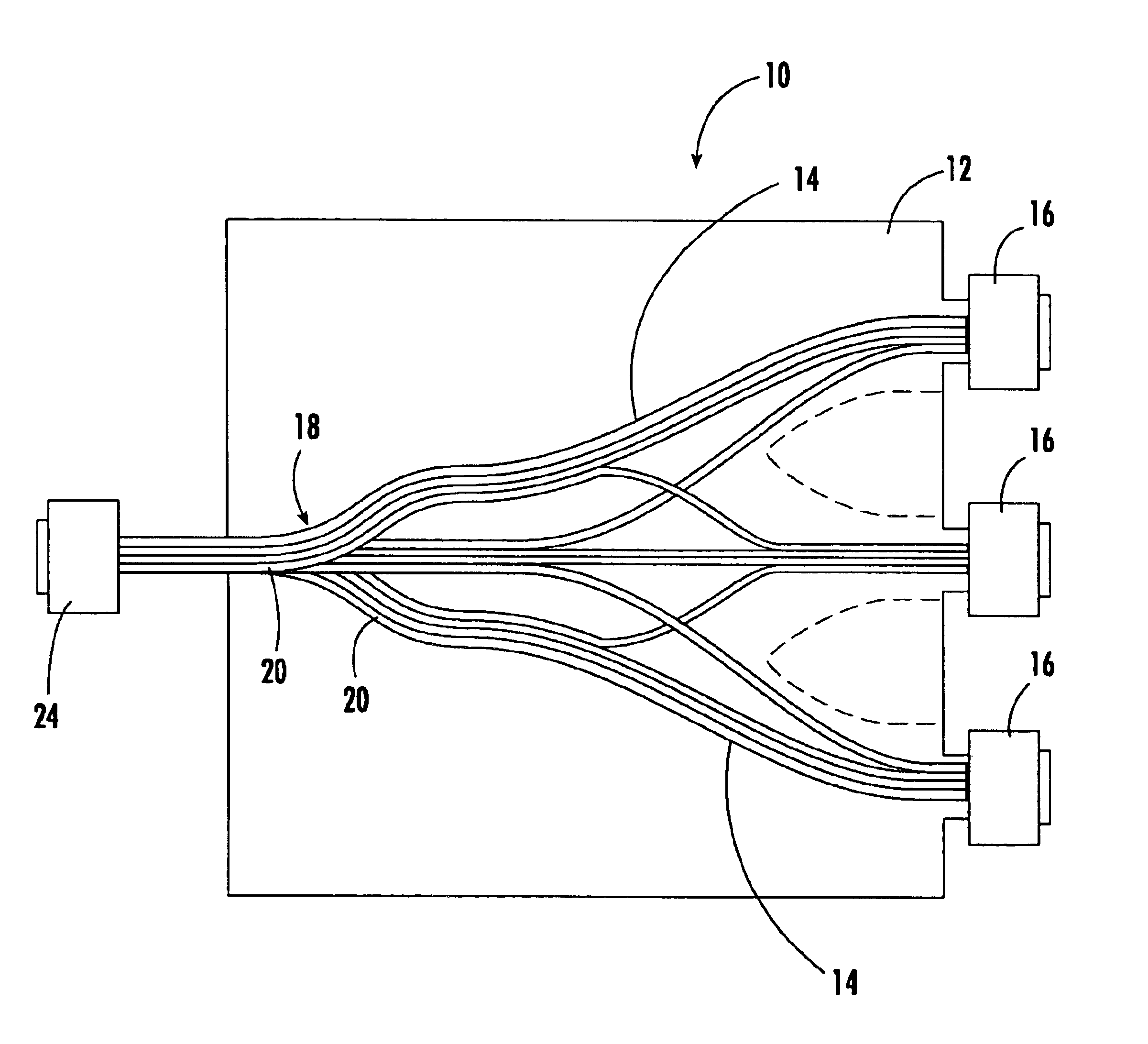
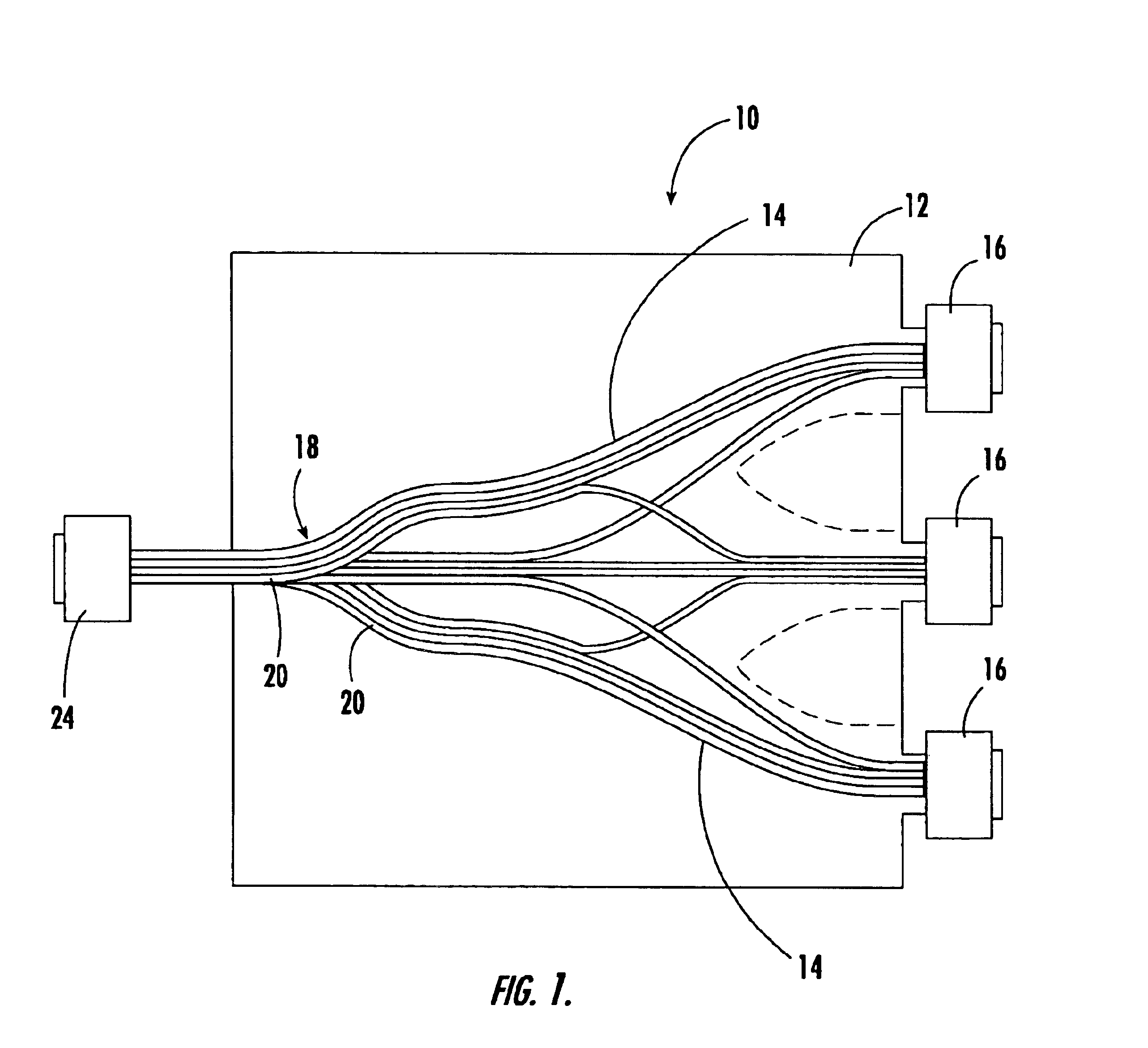
Referring now to FIG. 1, an optical circuit 10 according to one advantageous embodiment of the present invention is illustrated. The flexible optical circuit can be deployed in a variety of applications in order to route optical fibers in an organized and managed fashion. For example, the flexible optical circuit may permit a plurality of ribbons of optical fibers to be interconnected or cross-connected. As such, the flexible optical circuit may be utilized as a...


PUM


Abstract

An optical circuit is provided having a plurality of legs, each of which may have one or more optical fibers bound together by a matrix material, arranged in a stacked configuration in such a manner as to reduce, if not eliminate, the stress to which the optical fibers are subjected. The optical circuit includes a main body having a flexible substrate and a plurality of optical fibers mounted upon the substrate and lying in a common plane. The plurality of legs extend outwardly from an edge of the main body. The legs are disposed in a stacked configuration in which at least one leg overlies another leg. As such, at least one leg lies at least partially outside of the common plane defined by the substrate. A method for fabricating the optical circuit is also provided.

Description

FIELD OF THE INVENTIONThe present invention relates generally to flexible optical circuits and associated fabrication methods and, more particularly, to flexible optical circuits having a plurality of legs disposed in a stacked configuration.BACKGROUND OF THE INVENTIONFlexible optical circuits are utilized in a wide variety of applications in which fiber management is desirable. For example, flexible optical circuits are commonly utilized as optical back planes to interconnect a number of printed circuit boards or the like. Similarly, flexible optical circuits can serve as ribbons of optical fibers in order to route the optical fibers in an organized fashion.Regardless of the application, a flexible optical circuit is commonly formed of a plastic substrate, typically formed of a polyimide or similar types of engineering thermoplastic materials, such as polyetherimide or polybutylene terphthalate. Most commonly, however, the substrate is formed of Kapton™ polyimide. The substrate is ...

Claims


Application Information

Patent Timeline
Patent Type & Authority Patents(United States)
IPC IPC(8): G02B6/06G02B6/08G02B6/36G02B6/44
CPCG02B6/4472G02B6/366G02B6/3608G02B6/3668
Inventor CARNEVALE, SHARONBUMGARNER, RANDYHUGHES, MICHAELSOROSIAK, JAMES L.
Owner US CONEC
Why Eureka
Try Eureka