Crimped, prismatic battery structure

a prismatic and battery technology, applied in the field of batteries, can solve the problems of low cost, inability to easily configure flexible packages in stacked configurations, and inability to meet the requirements of electrical vehicles and other, and achieve the effect of facilitating the stacking of assembled housings

Active Publication Date: 2013-11-07
A123 SYSTEMS LLC
View PDF3 Cites 46 Cited by
  • Summary
  • Abstract
  • Description
  • Claims
  • Application Information

AI Technical Summary

Benefits of technology

[0009]In particular instances, the rectangular bottom face of the base member is configured so that its length is at least twice its width. In specific instances, the side wall is configured so as to define a recessed step portion at its junction with the base, and this step portion may, in particular instances, comprise no more than 20% of the total side wall height. The cover member may also include a recessed perimeter portion which defines a central, recessed, portion which corresponds to the stepped portion so as to facilitate stacking of the assembled housings.

Problems solved by technology

While housings of this type are lightweight and low in cost, such packages tend to be permeable to moisture and oxygen, and problems are also encountered at the points at which electrode tabs or other structures must protrude from the package to allow for tapping of electrical current.
Furthermore, such flexible packages can not readily be configured in stacked configurations.
As such, such flexible packages are not generally employed in electrical vehicles and other such high power and / or long service life applications.
However, certain problems do arise in connection with the use of metal battery housings.
However, cylindrical battery structures do not provide for maximum packing density as may be required in electrical vehicle applications.
Cost has been a significant problem, which has limited the use of such prismatic battery structures since their construction typically requires the use of relatively expensive, deep drawn metal structural components.
In addition, sealing of such structures is typically required to be implemented by relatively expensive processes such as laser welding.

Method used


Image

  • Crimped, prismatic battery structure
  • Crimped, prismatic battery structure
  • Crimped, prismatic battery structure

Examples


Embodiment Construction

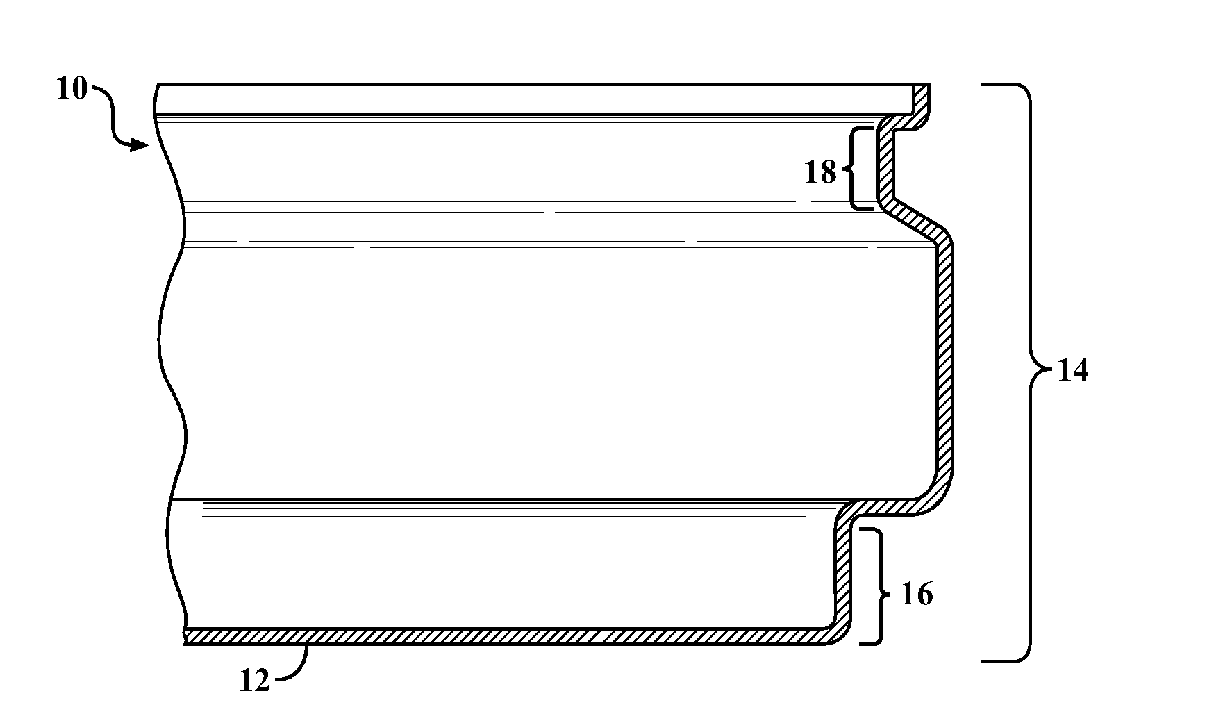
[0025]The battery housings of the present invention are configured so as to provide a battery structure which may be readily assembled into stacks of series and / or parallel connected batteries such that the stacks provide very good electrical contact, efficient use of space, and optimize heat dissipation. The structures of the present invention may be fabricated without the use of expensive metal forming techniques such as deep drawing techniques and may be readily assembled into reliable, sealed battery structures. The battery housings of the present invention may be implemented in a number of different configurations. The principles of the present invention will be explained with reference to some specific embodiments, and it is to be understood that other embodiments are within the scope of this invention.

[0026]Referring now to FIG. 1, there is shown a partial cross-sectional view of one embodiment of base member 10 which may be utilized in the present invention. This base member...


PUM

PropertyMeasurementUnit
lengthaaaaaaaaaa
lengthaaaaaaaaaa
heightaaaaaaaaaa

Abstract

A battery housing is comprised of a unitary, seamless base member having a generally planar, quadrilateral bottom face with a side wall extending therefrom. The length dimension of the bottom face is at least twice the height of the side wall. The base member has an open top face. The housing includes a cover which closes the open top face and is engageable with the side wall of the base. An electrically resistive sealing gasket is configured to contact the cover member and the side wall so as to provide a fluid-tight seal. The components are mechanically interlocked by crimping or hemming. The housing is specifically configured to accommodate stacking of individual batteries into power assemblies, and the geometry of the housing optimizes thermal management. Further disclosed are batteries and battery assemblies including the housing.

Description

CROSS-REFERENCE TO RELATED APPLICATIONS[0001]This application claims priority of U.S. Provisional Patent Application Ser. No. 61 / 351,526, filed Jun. 4, 2010, and entitled “Crimped, Prismatic Battery Structure”, the disclosure of which is incorporated herein by reference.FIELD OF THE INVENTION[0002]This invention relates generally to battery systems. More specifically, the invention relates to a battery module which employs a particular housing construction based upon a crimped, sealed structure and to power systems based on assemblages of such modules.BACKGROUND OF THE INVENTION[0003]The housing of a battery functions to retain and protect the electrochemically active components of a battery stack while also allowing for extraction of electrical power therefrom. The battery housing isolates the electrolytes and other potentially reactive components of the battery from oxygen, moisture, and other detrimental components of an ambient atmosphere. A battery housing should be lightweight...

Claims


Application Information

Patent Timeline
Patent Type & Authority Applications(United States)
IPC IPC(8): H01M2/02H01M50/103H01M50/167H01M50/553
CPCH01M2/024Y10T29/4911Y02E60/10H01M50/103H01M50/171H01M50/553H01M50/167H01M50/119H01M50/159H01M50/193
Inventor VU, VIET
Owner A123 SYSTEMS LLC
Why Eureka
Try Eureka