[0011]The triangular structures described in this disclosure may be used for fixation of a single bone, or for anchoring to a single bone, to provide a rigid anchor at the bone. This can typically be used for providing external connections to the bone, by means of which other elements may be connected. In such examples, the first two sides of the triangular structure preferably pass through two regions of the bone to be fixated, with those two sides being firmly connected at their apex (or vertex), and the third side of the triangle is preferably rigidly connected to those ends of the first two sides opposite to the joined apex ends. The third side may be executed by means of a physically separate external connector rod making up the third side. Alternatively, the third side can be a “virtual third side”, generated by firmly fixing to the bone each of the ends of those first two sides opposite to the joined apex ends, such that the intervening bone between those two opposite ends of the first two sides constitutes the structure of the third side. Once such a structure has been formed in a single
vertebra, the outer portion of the structure can be used as support points for attaching other elements for connection to other
bone structures, such as to other neighboring vertebrae. Typically, a triangular
system having all three of its apexes joined, provides an efficient
load sharing structure in which all of the sides take part, significantly reducing local stress and therefore reducing loosening and breakage of either bone or of the
implant elements. By this means, it is possible to perform conventional
spinal fusion using connecting rods, but with the connecting rods attached to the triangular structure instead of by means of screws driven into the pedicles. This generally can provide more strength, rigidity, durability and resistance to loosening, besides being a generally
safer procedure.
[0012]There exist in
spinal surgery, methods and systems for
motion preservation, whereby, rather than fusing neighboring vertebrae by which
relative motion is compromised, the
relative motion between
vertebra is preserved, often by means of replacement
facet joints using posterior dynamic stabilization elements. Such systems generally rely on pedicle screws for connection to the vertebra. Since such systems are intended for long dynamic use, and are subject to
continuous dynamic stresses as the vertebrae move relative to each other, the need to
resist loosening, breakage, or pull-out is even more important than for fusion attachments. According to further implementations, triangular structures of with arcuate elements may be used for fixing the elements of the
motion preservation replacement joints to the vertebrae, resulting in a more robust fixing method, with longer, trouble-free lifetime, thus substantially improving such
motion preservation systems.
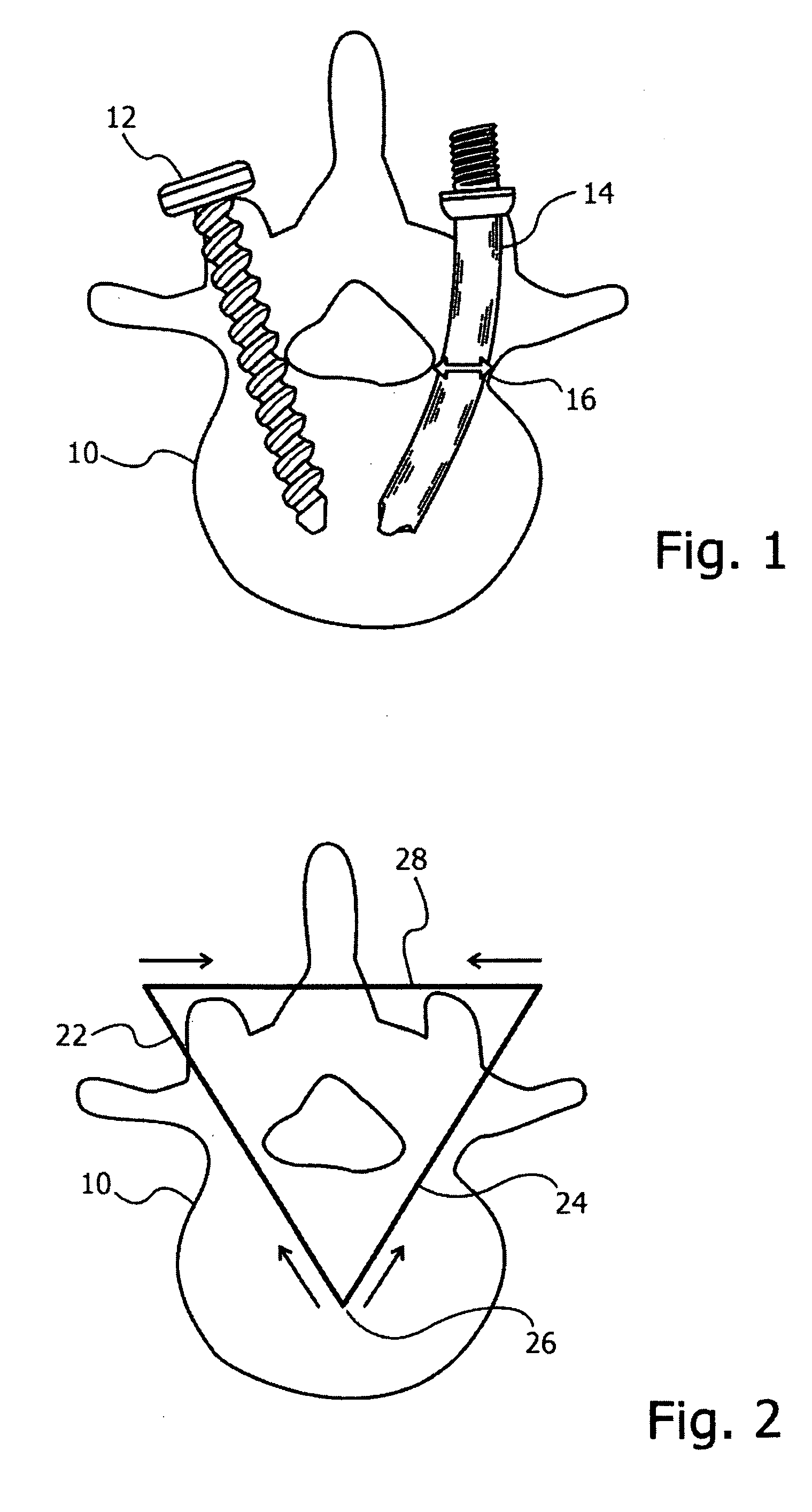
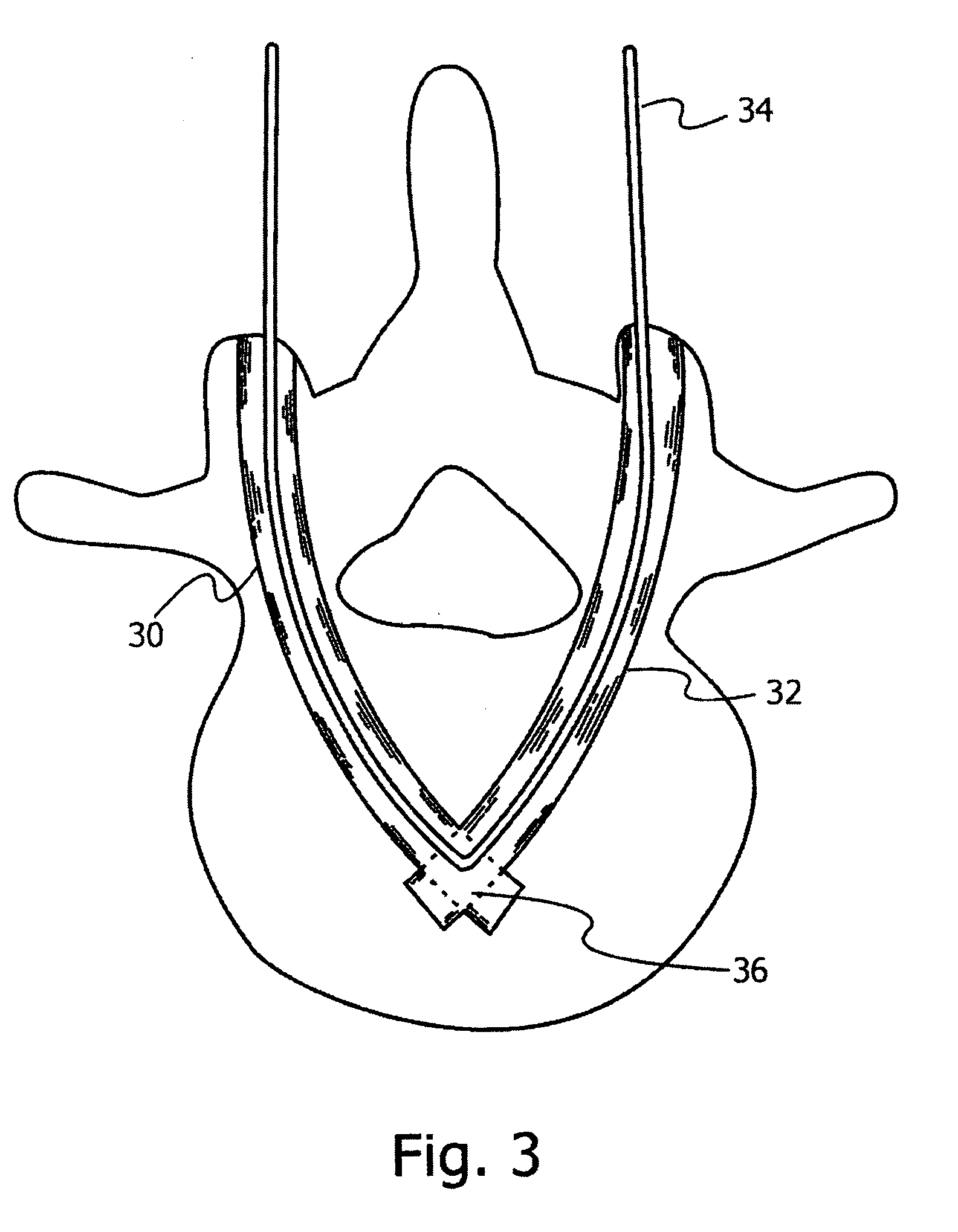
[0014]Furthermore, when applied to
spinal surgery, methods and structures using arcuate-shaped elements, such as is described in this application, enable posterior entry of the structural elements, with their distal ends anchored at the anterior portions of the
vertebral body or disc region, yet without encroaching on the
spinal cord channel because of the curved shape of the elements. This aspect represents a substantial improvement over the prior art use of arcuate elements in
spinal surgery, where anterior entry is generally used in order to avoid approaching the spinal channel. Such anterior access is generally achieved only by substantial
surgical procedures. The posterior arcuate element structures described in this application, on the other hand, can be inserted using minimally invasive
surgical procedures on the patient's back.
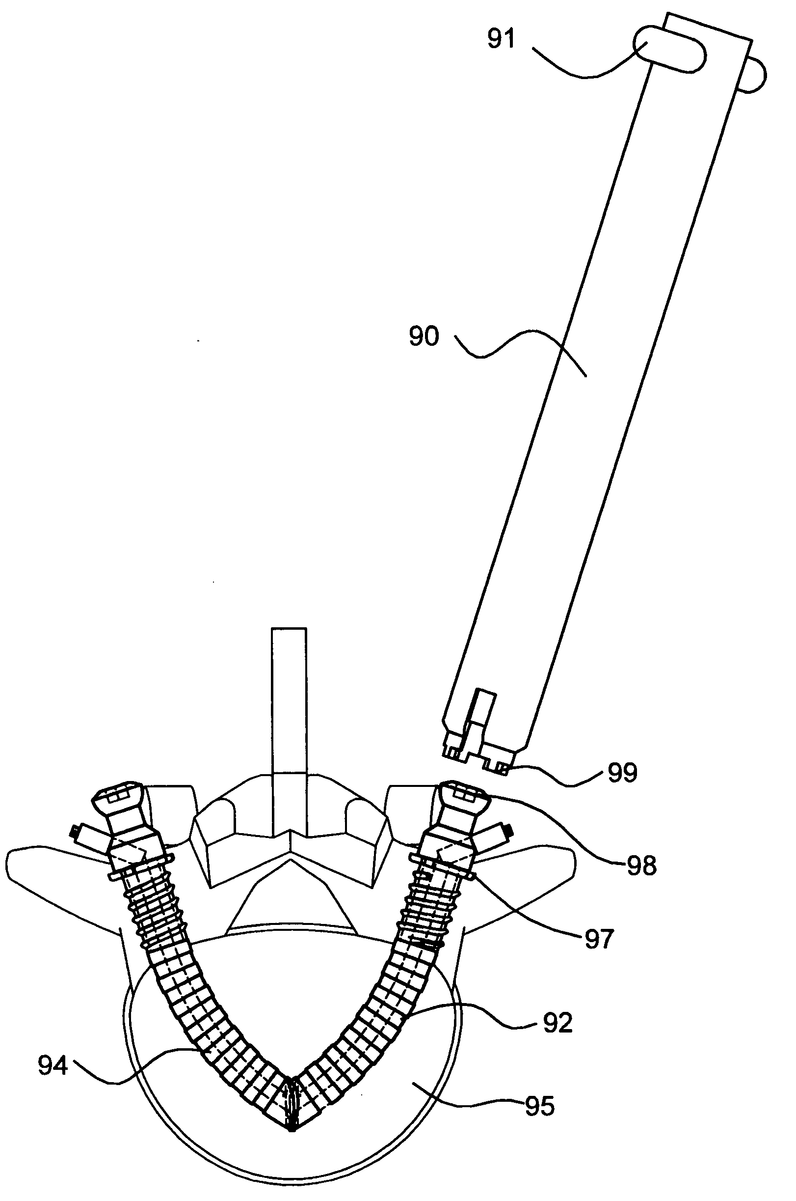
[0016]A further
advantage of the use of the wire connected triangular structure is that at any time during the lifetime of the
implant, if it is necessary to remove the implant elements, this can be done simply by releasing the wire at the proximal end of an insert, whereupon the arcuate arms can be slid or worked out of their channels without the need for surgical intervention at or
surgical access to the
joint point of the elements at the apex.
[0042]For such an element, the screwing of the thread into the bone may be used to pull the element into the channel. This screwing of the thread into the bone may also assist in anchoring the element into the bone.

