Biologically inspired gripping device

a technology of gripping device and biological organism, which is applied in the field of control devices, can solve the problems of affecting the gripping effect of biological organisms, affecting the gripping effect of objects, and deforming the gripping surface, and achieves the effect of cleaning the plumbing

Active Publication Date: 2006-01-05
CASE WESTERN RESERVE UNIV
View PDF10 Cites 62 Cited by
  • Summary
  • Abstract
  • Description
  • Claims
  • Application Information

AI Technical Summary

Benefits of technology

[0010] It is a further aspect of the present invention to provide a biologically-inspired gripper device that can transfer pliable materials through a lumen.
[0011] It is a still further aspect of the present invention to provide a biologically-inspired gripper device that can surgically remove plaque from blood vessels and clean plumbing.
[0012] The present invention relates to a gripping device that is based on the feeding apparatus of a mollusk, known as the buccal mass. The device consists of fo

Problems solved by technology

A difficulty with such prior art devices is that they may crush, deform, or in other ways change the properties of the object that has be

Method used


Image

  • Biologically inspired gripping device
  • Biologically inspired gripping device
  • Biologically inspired gripping device

Examples


first embodiment

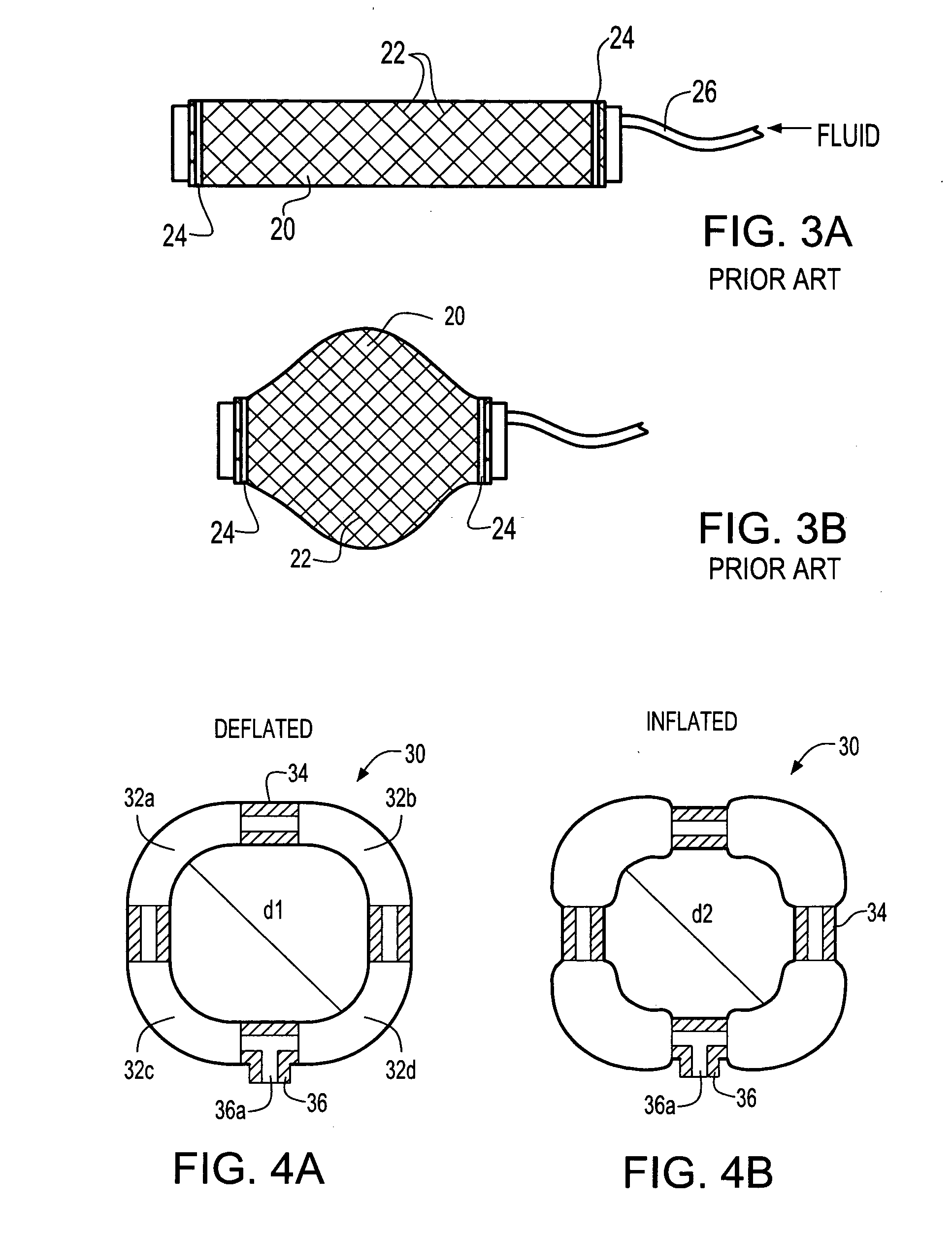
[0047] Referring to FIGS. 5A and 5B, there is illustrated the grasper element 40 (corresponding to element 14). The grasper element 40 incorporates a pair of inflatable, lip-like tubular actuators 42 and 44 constructed similar to the braided pneumatic actuators shown in FIG. 3A. The inflatable, lip-like tubular actuators 42 and 44 are disposed around a relatively rigid ellipsoid shaped element 46, such as one formed from rubber. At the approximate center of the ellipsoid 46, there is a groove 47 with a flat bottom surface formed around the circumference of the ellipsoid. The groove 47 is disposed parallel to the minor axis of the generally ellipsoid shaped element. Disposed within the groove 47 are a pair of tubular actuators 42 and 44 that are placed against the edge walls 47a and 47b of groove 47 and held in place by any desired means such as a rubber band 48 secured to opposite ends of the actuators or artificial muscles 42 and 44. The actuators 42 and 44 extend around the circum...

second embodiment

[0048] a hinged grasper element 50 (corresponding to element 14) is shown in FIGS. 6A and 6B. The hinged grasper element 50 is constructed of a generally spherically shaped, flexible element 51, such as an elastomeric or rubber ball. The spherically shaped element 51 has a cleft opening 52 formed therein. The cleft opening 52 typically has a generally wedge like shape that extends from the peripheral surface 54 of the spherically shaped element 51 to a location near a centerline 55 extending through the spherically shaped element. The angle “a” of the wedge shaped opening 52 is preferably between about 5° to about 45° and preferably about 15° to about 40° and most preferably about 25° to about 35°. On the opposite side of the spherically shaped element 51 from the wedge shaped opening 52 is formed a second cleft opening 56, generally of a wedge like shaped which can be substantially identical to the cleft opening 52. There is a small section of flexible material separating the cleft...


PUM


Abstract

The present invention relates to a gripping device that consists of four artificial muscle rings arranged in parallel. A grasper is placed in the middle of the rings. Sequential activation of the rings produces a peristaltic motion that moves the grasper back and forth within the rings. By activating the grasper appropriately, it can grab, ingest, and move soft and irregular material from one side of the lumen formed by the rings to the other side.

Description

CROSS-REFERENCE TO RELATED APPLICATIONS [0001] This application claims the benefit of U.S. Provisional Patent Application No. 60 / 584,281 filed on Jun. 30, 2004, which is incorporated herein by reference.FEDERALLY SPONSORED RESEARCH [0002] The contents of this application were developed under a Presidential Research Initiative Grant, NSF Grant IBN99-74394 and NSF grant IBN-0218386.FIELD OF THE INVENTION [0003] The present invention relates to control devices, and specifically to control of devices that are capable of gripping and manipulating materials. BACKGROUND OF THE INVENTION [0004] A major focus of robotic applications is the development and control of devices that are capable of gripping and manipulating materials. Basic grippers consist of two surfaces that can be brought together; more dextrous grippers use fingers, some of which can be individually controlled as disclosed in Causey, G., Guidelines for the design of robotic gripping systems. Assembly Automation, 2003, 23: p....

Claims


Application Information

Patent Timeline
IPC IPC(8): A61B17/22
CPCA61B2017/00544A61B17/22032
Inventor CHIEL, HILLEL JUDAHBEER, RANDALL DEANMANGAN, ELIZABETH VICTORIAQUINN, ROGER D.SUTTON, GREGORY PATRICK
Owner CASE WESTERN RESERVE UNIV
Why Eureka
Try Eureka