Headgear having airflow characteristics

a technology of airflow and headgear, which is applied in the field of headgear, can solve the problems of current hats or caps, their tendency to be blown off, and not working,

Inactive Publication Date: 2006-01-12
STEPHENSON MICHAEL
View PDF13 Cites 9 Cited by
  • Summary
  • Abstract
  • Description
  • Claims
  • Application Information

AI Technical Summary

Benefits of technology

[0023] To achieve the foregoing and other advantages, the present invention, briefly described, provides a visor or cap brim that prevents the pressure of the wind from blowing the cap off of the user's head. The visor portion is a generally planar surface that is held out away from the front of the cap portion that sits on the user's head. This creates a single large passage between the visor / bill and the cap and the visor / bill is held at such an angle that it acts a “spoiler” to press the hat down more firmly on the user's head in a high wind while at the same time shading the eyes and forehead from the sun. The visor portion of the cap is removably attached to a semi-rigid headband that encircles the base of the main body of the cap. This attachment is accomplished by a rivet-type attachment means at the terminal ends of a pair of arms attached to the visor portion.

Problems solved by technology

One of the primary disadvantages of current hats or caps is their tendency to be blown off during periods of high wind.
In the case of a man's shorter hair, or hair that is not sufficiently thick or piled up on the head, this will not work.
As in all the other patents discussed here, this also does not teach the unique structure of applicant's brim, which is located such that an air space is created between the brim and the cap body.

Method used


Image

  • Headgear having airflow characteristics
  • Headgear having airflow characteristics
  • Headgear having airflow characteristics

Examples


Embodiment Construction

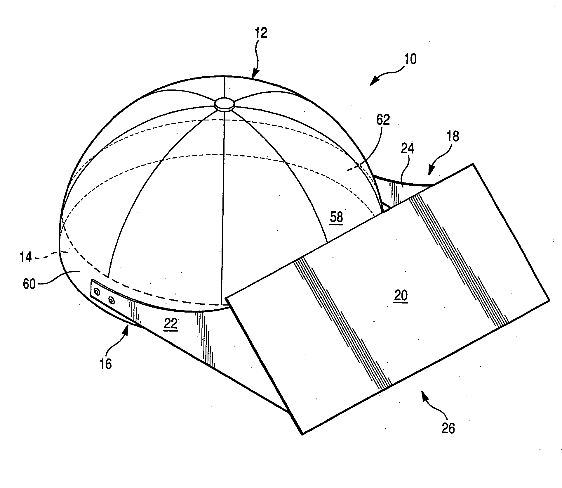
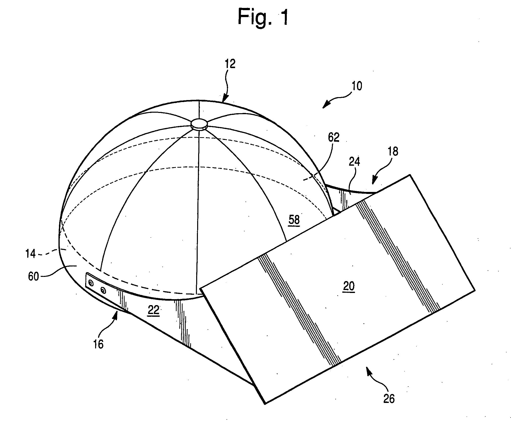
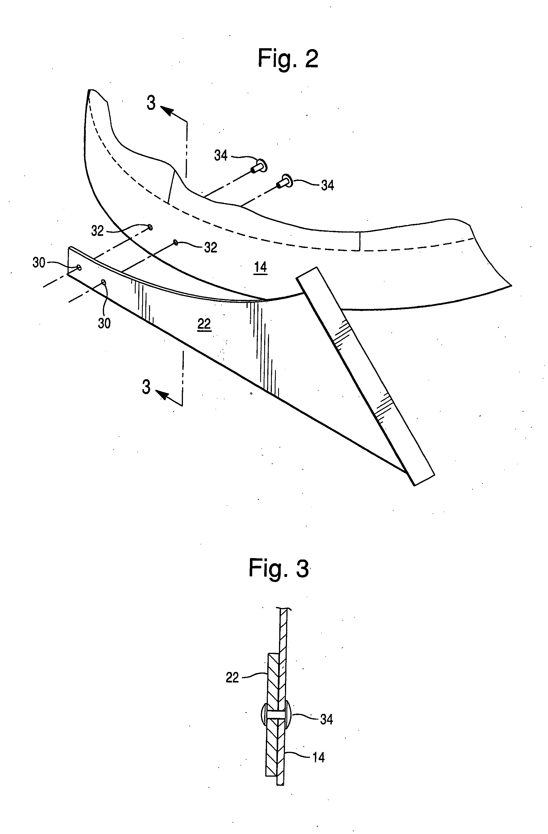
[0036] Referring first to FIG. 1 the invention is indicated generally at 10. The main body of the cap 12 is a dome-shaped cap of the type sometimes referred to as a “beanie”. It should be understood at the outset, however, that the shape of this main body portion of the cap does not form part of the inventive structure of the instant invention and that the invention is not limited to this type and many other shapes for head covering would occur to the skilled practitioner. Included near the base of the cap body 12 is a semi-rigid headband, shown in FIG. 1 in dotted outline and indicated at 14. This headband 14, which could be made out of any number of suitable materials such as plastic or paper, encircles the base 16 of the main cap body 12.

[0037] The discussion, still referring to FIG. 1 now turns to the visor portion of the headgear 10. This visor portion is indicated generally at 18 and includes the main visor portion 20, first arm 22, and second arm 24. Main visor portion 20 is...


PUM


Abstract

A visor or cap brim is disclosed that prevents the pressure of the wind from blowing the cap off of the user's head. The visor portion is a generally planar surface that is held out away from the front of the cap portion that sits on the user's head. This creates a single large passage between the visor / bill and the cap and the visor / bill is held at such an angle that it acts a “spoiler” to press the hat down more firmly on the user's head in a high wind while at the same time shading the eyes and forehead from the sun. The visor portion of the cap is removably attached to a semi-rigid headband that encircles the base of the main body of the cap. This attachment is accomplished by a plastic “rivet” type arrangement connected at the terminal ends of a pair of arms attached to the novel visor portion. The visor portion includes a wind or air dam along its upper edge to increase stability and is also slidable up and down the arms.

Description

BACKGROUND OF THE INVENTION [0001] 1. Field of the Invention [0002] The present invention relates generally to headgear. More specifically, it relates to headgear wherein the brim or sunshade portion of the hat is not connected directly to the front portion of the hat proximate the user's forehead, but is only attached at the sides of the hat, i.e. proximate the user's ears. This shading portion of the hat is angled to provide both protection from the sun and to prevent the cap or hat from being dislodged by the wind. [0003] 2. Description of the Prior Art [0004] One of the primary disadvantages of current hats or caps is their tendency to be blown off during periods of high wind. The brim of the hat, or the portion designed to protect the user's eyes and forehead from the wind, creates a lifting surface that tends to lift the hat off the head. One of the comic standards of the silent film era is that of the hatless man chasing the errant item of apparel down the street during a win...

Claims


Application Information

Patent Timeline
Patent Type & Authority Applications(United States)
IPC IPC(8): A42B1/06
CPCA42B7/00A42B1/062A42B1/0182
Inventor STEPHENSON, MICHAEL
Owner STEPHENSON MICHAEL
Why Eureka
Try Eureka