Liquid crystal display

a technology of liquid crystal display and display face, which is applied in the field of liquid crystal display apparatus, can solve the problems of unevenness on the display face, problem that cannot be solved, and inferior panel to cathode ray tube, and achieve the effect of restricting the unevenness of the display screen

Inactive Publication Date: 2006-01-12
JAPAN DISPLAY CENTRAL CO LTD
View PDF21 Cites 19 Cited by
  • Summary
  • Abstract
  • Description
  • Claims
  • Application Information

AI Technical Summary

Benefits of technology

[0088] According to the present invention, it is possible to provide a liquid-crystal-panel drive, a driving method and its program, and a recording medium capable of restraining the unevenness of a display screen after turning off a power supply in a liquid crystal display apparatus using OCB mode liquid crystal.
[0089] Moreover, according to the present invention, it is possible to provide a liquid-crystal-panel driver, driving method and its program, and a recording medium in a liquid crystal display apparatus using OCB mode liquid crystal in which a display face can quickly change from bend orientation to splay orientation after turning off a power supply.

Problems solved by technology

Therefore, the panel is inferior to a cathode ray tube because it leaves traces for animation display.
Therefore, this problem is not solved by only turning on gates of TFTs.
Specifically, unevenness has been recognized on a display face unless the process in which the bend orientation used for display of the OCB mode liquid crystal transitions to the splay orientation is uniform.
Particularly, because an image ununiformly disappears from a display face depending on a display pattern, uncomfortable feeling occurs to a user.
First, when a voltage to be applied to the OCB mode liquid crystal becomes 0 V, the bend orientation becomes unstable and 180° twist occurs in all regions.
A problem is that a state in which the twist orientation (yellow) and splay orientation (blue) after turning off the power supply are mixed is seen as an uneven state on a display face ununiformly or depending on the pattern at the time of display.
In this case, when external light is strong, the difference between orientation states of various portions of the liquid crystal layer is seen as unevenness even if turning off the backlight.
Moreover, when turning on the power supply again, in a time until completely changing to the splay orientation after turning off the power supply, a long transfer driving period of changing to the bend orientation is necessary when the power supply is turned on and an excessive time is required until an image is displayed after turning on the power supply.

Method used


Image

  • Liquid crystal display
  • Liquid crystal display
  • Liquid crystal display

Examples


embodiment 1

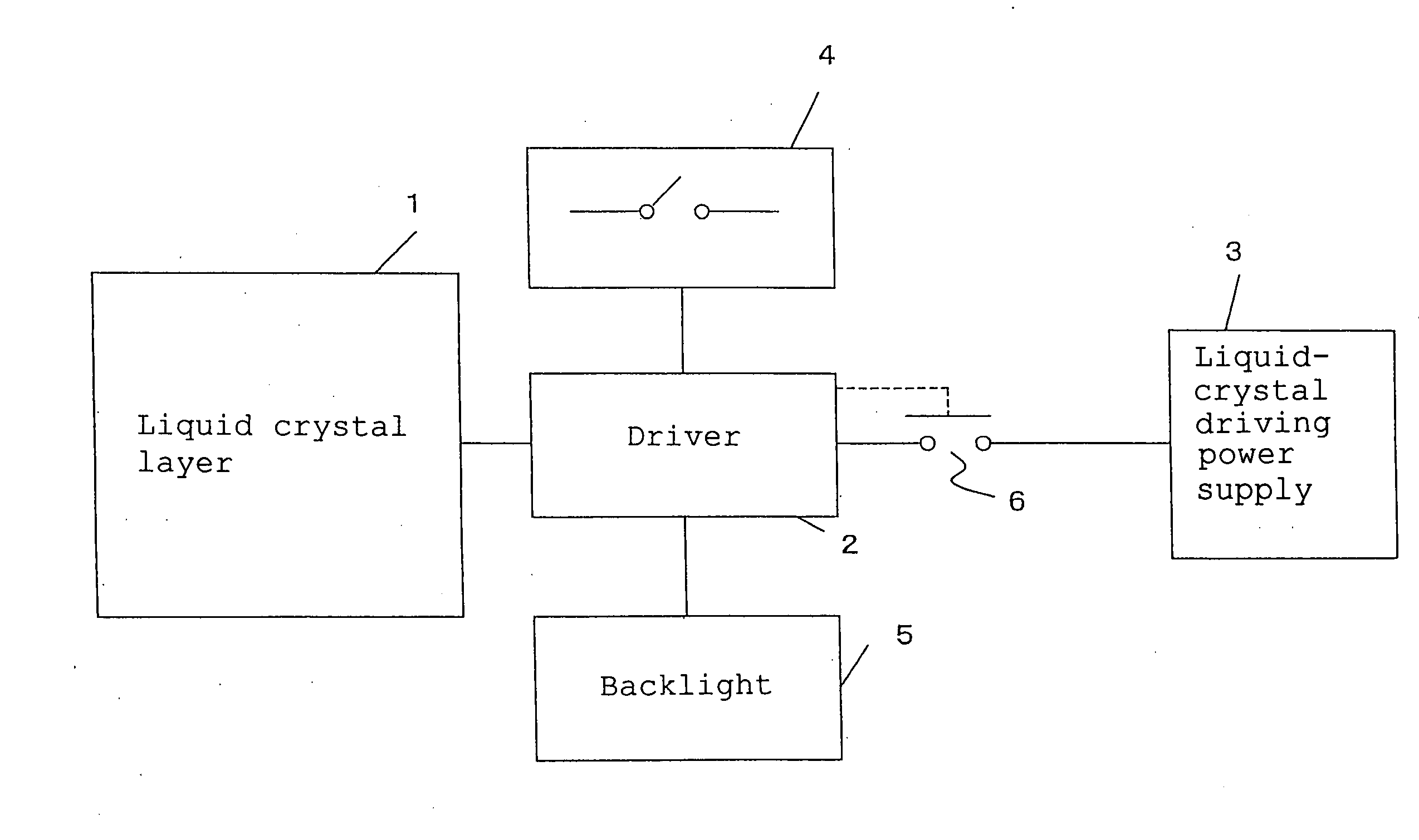
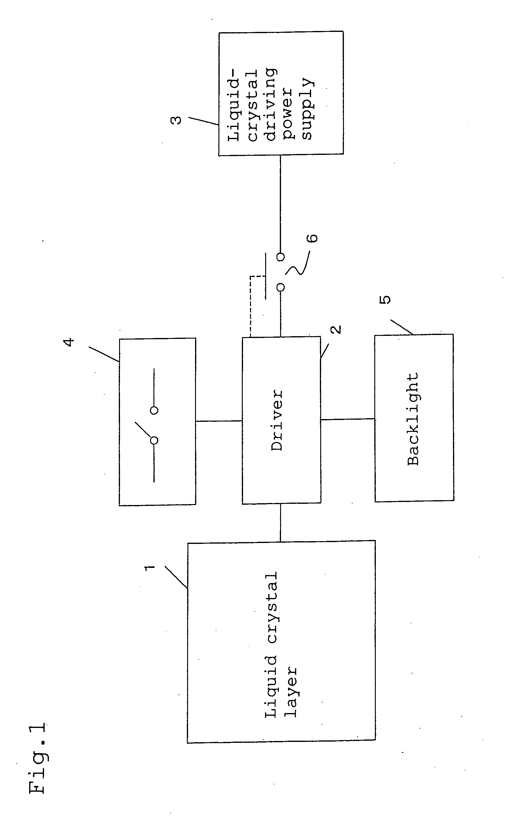
[0118]FIG. 1 is a block diagram showing a configuration of the liquid crystal display apparatus of the embodiment 1 of the present invention. A driver 2 which is an example of a driver of the present invention of applying a voltage to a liquid crystal layer 1, which uses OCB mode liquid crystal, of an example of a liquid crystal layer of the present invention is connected to the liquid crystal layer 1. A backlight 5 of irradiating a display face constituted by the liquid crystal layer 1 and a switch 4 of turning on / off the power supply of the liquid crystal display apparatus of the present invention are connected to the driver 2. A liquid crystal driving power supply portion 3 of a liquid crystal power supply of an example of a liquid crystal driving power supply of the present invention for supplying power to the driver 2 and the backlight 5 is connected to the driver 2 through a switch 6.

[0119]FIG. 6 is a circuit diagram showing a configuration of the liquid crystal layer 1. A so...

embodiment 2

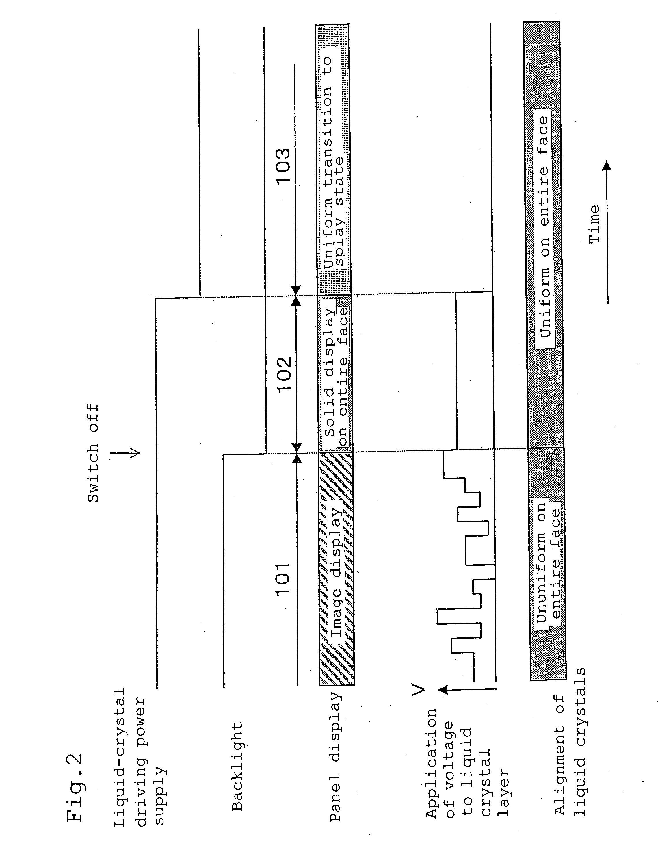
[0133]FIG. 3 shows a time chart of the power supply OFF sequence of a liquid crystal display apparatus of embodiment 2 of the present invention.

[0134] Because the configuration of the liquid crystal display apparatus of this embodiment is the same as that of the liquid crystal display apparatus of the embodiment 1, its description is omitted.

[0135] In the image display period 201 shown in FIG. 3, various voltages for displaying an image on a display face are applied to the liquid crystal layer 1 from the driver 2. That is, because voltages to be applied to the liquid crystal layer 1 differ in the region of the liquid crystal layer depending on an image to be displayed, the alignment of liquid crystals becomes ununiform.

[0136] When the switch 4 is turned off, the driver 2 completes the image display period 201, turns off the backlight 5, and starts an OFF sequence period 202. In the OFF sequence period 202, the driver 2 applies a voltage equal to or lower than a maximum voltage wh...

embodiment 3

[0142]FIG. 4 shows a time chart of a power-supply OFF sequence of a liquid crystal display apparatus of embodiment 3 of the present invention. In FIG. 4, reference character (a) denotes operations of a liquid crystal driving power supply and a backlight, (b) denotes operations of a panel display, (c) denotes a voltage applying operation to a liquid crystal layer, and (d) denotes a change of potentials of each electrode.

[0143] Because a configuration of the liquid crystal display apparatus of this embodiment is the same as that of the liquid crystal display apparatus of the embodiment 1, its description is omitted.

[0144] In the image display period 301 shown in FIG. 4, various voltages are applied from the driver 2 to the liquid crystal layer 1 to display an image on a display face. That is, because voltages to be applied to the liquid crystal layer 1 differ in the region of the liquid crystal layer depending on an image to be displayed, the alignment of liquid crystals is ununifor...


PUM

PropertyMeasurementUnit
twist angleaaaaaaaaaa
time t1aaaaaaaaaa
sizeaaaaaaaaaa

Abstract

A liquid-crystal-panel drive, driving method and its program, and a medium capable of preventing unevenness on a display face from occurring after turning off a power supply in a liquid crystal display apparatus using OCB mode liquid crystal. A liquid crystal display apparatus has a liquid crystal layer using OCB mode liquid crystal, a driver applying a voltage to the liquid crystal layer, a liquid-crystal driving power supply supplying power to the driver, and a switch outputting an on/off signal to the driver. When the switch outputs an off signal, the driver applies a predetermined voltage that can be applied to each pixel of the liquid crystal layer for a predetermined time, and after the elapse of the predetermined time, stops the supply of power to the driver from the liquid-crystal driving power supply.

Description

TECHNICAL FIELD [0001] The present invention relates to a liquid crystal display apparatus, its stopping method, a program, and a recording medium. BACKGROUND ART [0002] A liquid crystal display apparatus is thin and lightweight and the number of its applications has been further increased in recent years as a substitute for a conventional cathode ray tube. A TN (Twisted Nematic) oriented liquid-crystal panel widely used at present has a small angle of visibility and a low response speed and its liquid-crystal element is the holding type. Therefore, the panel is inferior to a cathode ray tube because it leaves traces for animation display. [0003] In general, in the TN oriented liquid-crystal panel, a phenomenon has been observed that a display pattern remains even after turning off a power supply. When the liquid-crystal backlight goes out after turning off the power supply, a phenomenon, that is, an “OFF afterimage” occurs, in which display is thinly left and seen due to reflected ...

Claims


Application Information

Patent Timeline
Patent Type & Authority Applications(United States)
IPC IPC(8): G09G3/36G02F1/133G02F1/1333G02F1/139
CPCG02F1/13306G02F1/133707G02F1/1395G09G3/3648G09G2300/0426G09G2330/02G09G2300/0491G09G2310/0245G09G2310/06G09G2320/0247G09G2320/0257G09G2300/0486G02F1/139G02F1/137
Inventor KAWAGUCHI, SEIJINAKAO, KENJI
Owner JAPAN DISPLAY CENTRAL CO LTD
Why Eureka
Try Eureka