System and method for projector alignment

a projector array and projector technology, applied in the field of projectors, can solve the problems of increasing and exponentially difficult control of cumulative errors, and the downtime of the projector array

Inactive Publication Date: 2006-01-12
NORTHROP GRUMMAN SYST CORP
View PDF27 Cites 10 Cited by
  • Summary
  • Abstract
  • Description
  • Claims
  • Application Information

AI Technical Summary

Problems solved by technology

In-situ alignment of projectors relative to one another can, however, produce cumulative errors that are increasingly and exponentially difficult to control as the size of the projector array increases.
In-situ alignment of projectors can also result in downtime for the projector array when a projector is replaced, such as during repairs, and alignment of the replacement projector is required.

Method used


Image

  • System and method for projector alignment
  • System and method for projector alignment
  • System and method for projector alignment

Examples


Embodiment Construction

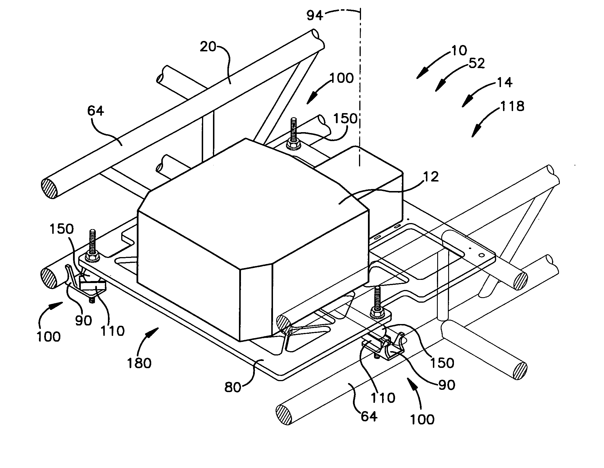
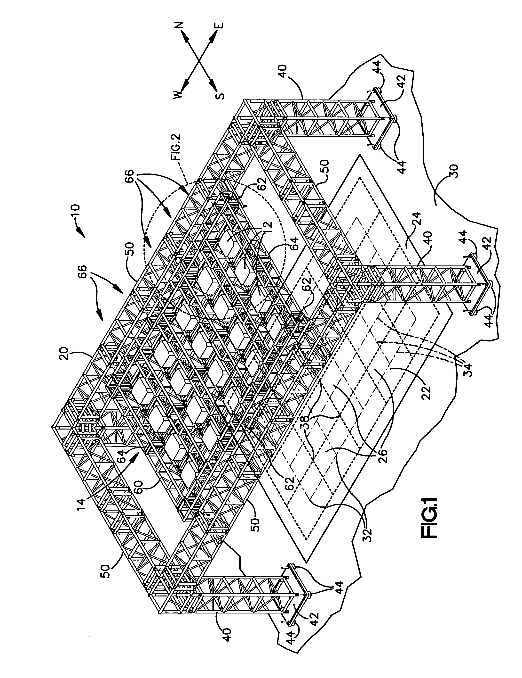
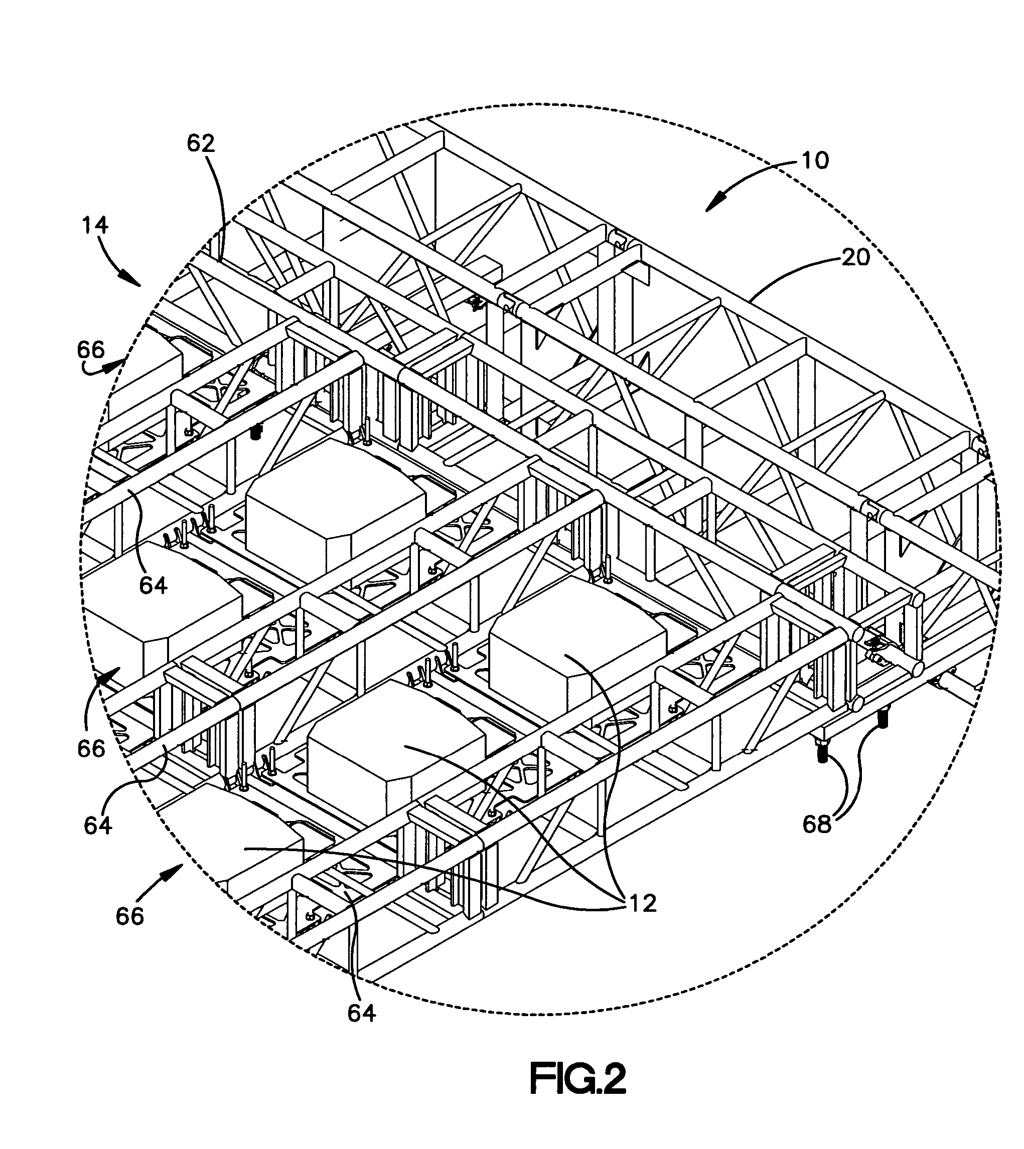
[0017] The present invention relates to a system and method for providing projector assemblies that can be interchangeably arranged in an array on a support structure, such as a truss system. The projector array projects a composite image on a projection surface that is positioned a given distance from the support structure. The composite image is composed of an array of adjacent component images, each of which is projected on the projection surface by a corresponding one of the projector assemblies in the projector array. The accuracy required at the projection surface can be about half a pixel or less. Considering that the projector assemblies in the projector array may be positioned a relatively long distance from the projection surface, higher accuracy may be required at the projector location than is required at the projection surface. Prior to installation, the projector assemblies and support structure are calibrated to a predetermined mechanical / optical configuration with a ...


PUM


Abstract

A system for supporting a projector on a support structure relative to a projection surface includes a plurality of base members connectable with the support structure and having a position adjustable relative to the projection surface. The system also includes a base member calibration system for calibrating the base members to a predetermined position relative to the projection surface. The system also includes a plurality of foot members for supporting the projector. Each foot member has a position adjustable relative to the projector. The system further includes a projector calibration system for calibrating the projector to a predetermined position relative to the foot members. The projector calibrated to the predetermined position relative to the foot members is calibrated to the predetermined position relative to the projection surface when the foot members rest on the base members.

Description

TECHNICAL FIELD [0001] The present invention relates generally to projectors and, more particularly, to a system and method for aligning projectors arranged in an array for producing a tiled composite image. BACKGROUND OF THE INVENTION [0002] Video projectors can be arranged in arrays of two or more projectors in order to project a tiled composite image in which each projector in the array projects a component image that forms a corresponding portion of the composite image. When projecting large images, video projector arrays can provide enhanced brightness and resolution of the composite image and can reduce the requisite distance between the projectors and the surface onto which the composite image is projected. When projecting a composite image via a projector array, it can be desirable to match or blend the adjacent edges of the component images in order to provide the appearance of a seamless composite image. [0003] The component image produced by each projector in the projecto...

Claims


Application Information

Patent Timeline
Patent Type & Authority Applications(United States)
IPC IPC(8): G03B23/08G03B21/14G03B21/22
CPCG03B21/14H04N9/3147G03B37/04G03B21/145
Inventor HARRISON, CHARLES FREDERICKFERREN, BRANHILLIS, W. DANIEL
Owner NORTHROP GRUMMAN SYST CORP
Why Eureka
Try Eureka