

Stabilizer II
a technology of stabilizer and stabilizer, applied in the field of stabilizer, can solve the problems of unabated flexibility withdrawal, contrary flexibility, and clearly shows the limitations of natural movement of the lower extremities
Inactive Publication Date: 2006-01-12
LAMPKINS GARY W
View PDF5 Cites 3 Cited by
- Summary
- Abstract
- Description
- Claims
- Application Information
AI Technical Summary
Problems solved by technology
This design displays, however, the draw back of unabated flexibility that will allow the foot and ankle to function in its normal capacity.
In point, flexibility is contrary to the designs purpose and function and clearly displays its limitations of natural movement of the lower extremities.
However effective, this invention by design does not incorporate individuals that are in need of flexible natural movement that is present when engaging in exercise or athletic activities.
Method used
View moreImage
Smart ImageViewing Examples

Examples
Embodiment Construction
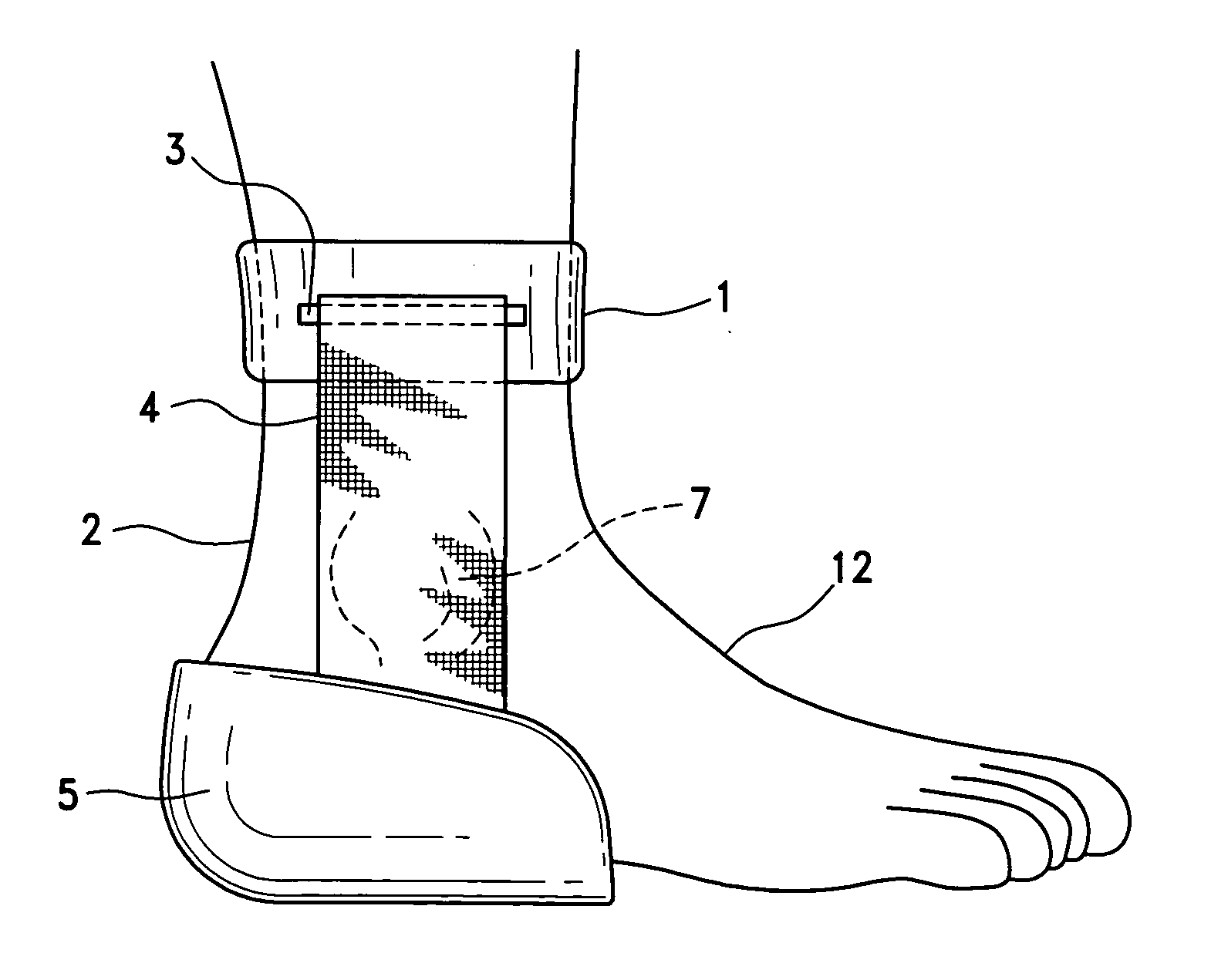
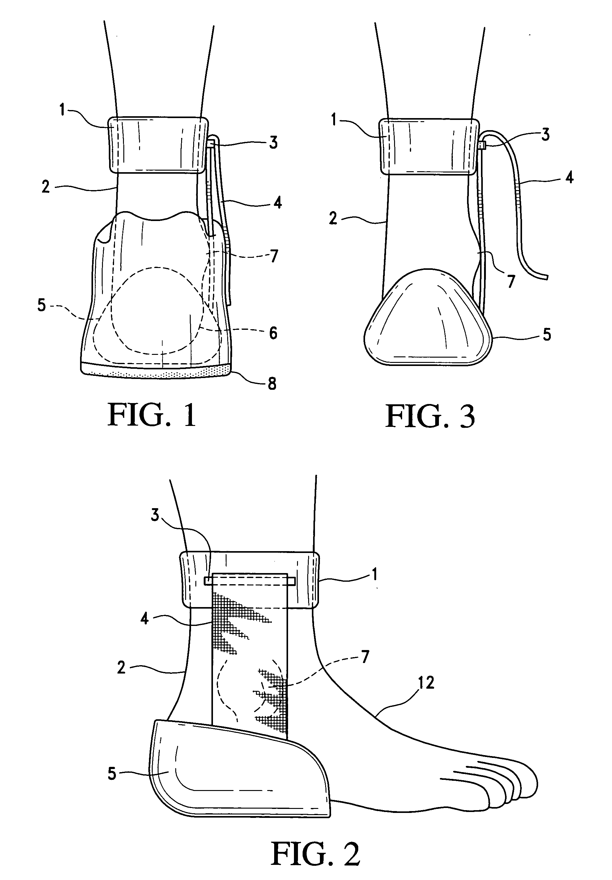
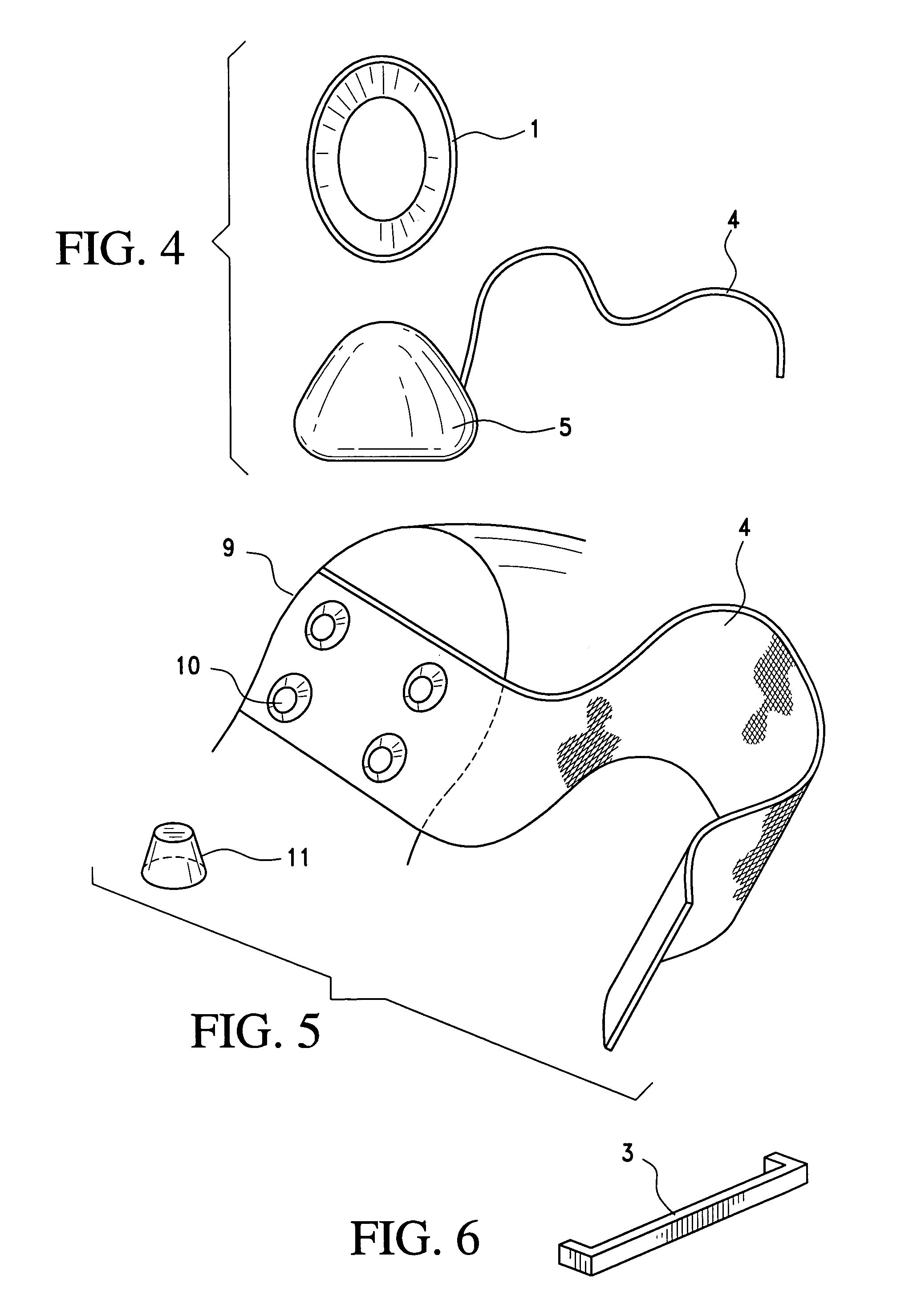
[0013] The apparatus includes a heel cup 5 within a shoe 8 with flex strap 4 attached to heel cup 5 with flex strap 4 ascending over ankle 7 and along the lower leg 2 being inserted under the leg strap anchor 3 which is attached to the adjustable leg attachment 1; once flex strap 4 is inserted under the leg strap anchor 3, the flex strap 4 will descend along the lower leg 2 while over lapping itself and finally attaching to the shoe 8. The virtue of the flex strap 4 being attached to the heel cup 5 and attached to the adjustable leg attachment 1 by way of being inserted under the leg strap anchor 3 and finally attaching to the shoe 8 will bring functionality, flexibility and most important, stability to the invention.
Login to View More PUM
 Abstract
A flexible orthopedic apparatus being made a part of a shoe that will help prevent the occurrence of ankle injury due to a twist while allowing full range of motion of the foot and ankle. The apparatus accomplishes this by placing an adjustable leg attachment to the lower leg and attaching a flexible strap to the leg attachment at one end and the bottom portion of the shoe on the other. By virtue of the design, the apparatus serves as a protective extra ligament that will aid in the prevention of ankle injury.
Description
BACKGROUND OF THE INVENTION [0001] The present invention relates to the stabilization and prevention of the foot and ankle rolling or turning to an injurious position while walking, running, jumping or participating in any physical activity that involves the lower extremity. The apparatus accomplishes this by attaching the lower foot to the lower leg with an adjustable, flexible extension that allows unabated foot and ankle movements. DESCRIPTION OF PRIOR ART [0002] U.S. Pat. No. 4,691,698, Bremer discloses a splint with a foot plate and rigid leg support to accommodate knock knee and control proration and suppuration of the leg, knee and foot. This design displays, however, the draw back of unabated flexibility that will allow the foot and ankle to function in its normal capacity. [0003] U.S. Pat. No. 3,805,773 Sichau discloses a training assist brace comprising of a rigid foot and heel member attached to stirrups that extend from the foot to the thigh, designed to limit and or pr...
Claims
Login to View More Application Information
Patent Timeline
 Patent Type & Authority Applications(United States)
IPC IPC(8): A61F5/00A43B7/20A61F5/01
CPCA61F5/0111A43B7/20
Inventor LAMPKINS, GARY W.
Owner LAMPKINS GARY W