Shotgun shell dispenser

a dispenser and shotgun shell technology, applied in the field of cartridge carriers, to achieve the effect of convenient dispense and refilling of cartridge carriers, and easy stacking together

Inactive Publication Date: 2006-01-19
ROGERS PAUL
View PDF11 Cites 10 Cited by
  • Summary
  • Abstract
  • Description
  • Claims
  • Application Information

AI Technical Summary

Benefits of technology

[0010] It is another object of the invention to provide such a carrier that allows a hunter to easily dispense and refill the carrier with one hand.
[0011] It is another object of the present invention to provide such a carrier that allows multiple carriers to be easily stacked together.

Problems solved by technology

Unfortunately, the dispensing mechanisms require the hunter to use both hands to refill the carrier.

Method used


Image

  • Shotgun shell dispenser
  • Shotgun shell dispenser
  • Shotgun shell dispenser

Examples


Embodiment Construction

)

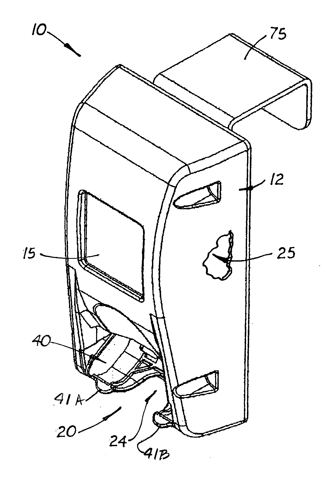
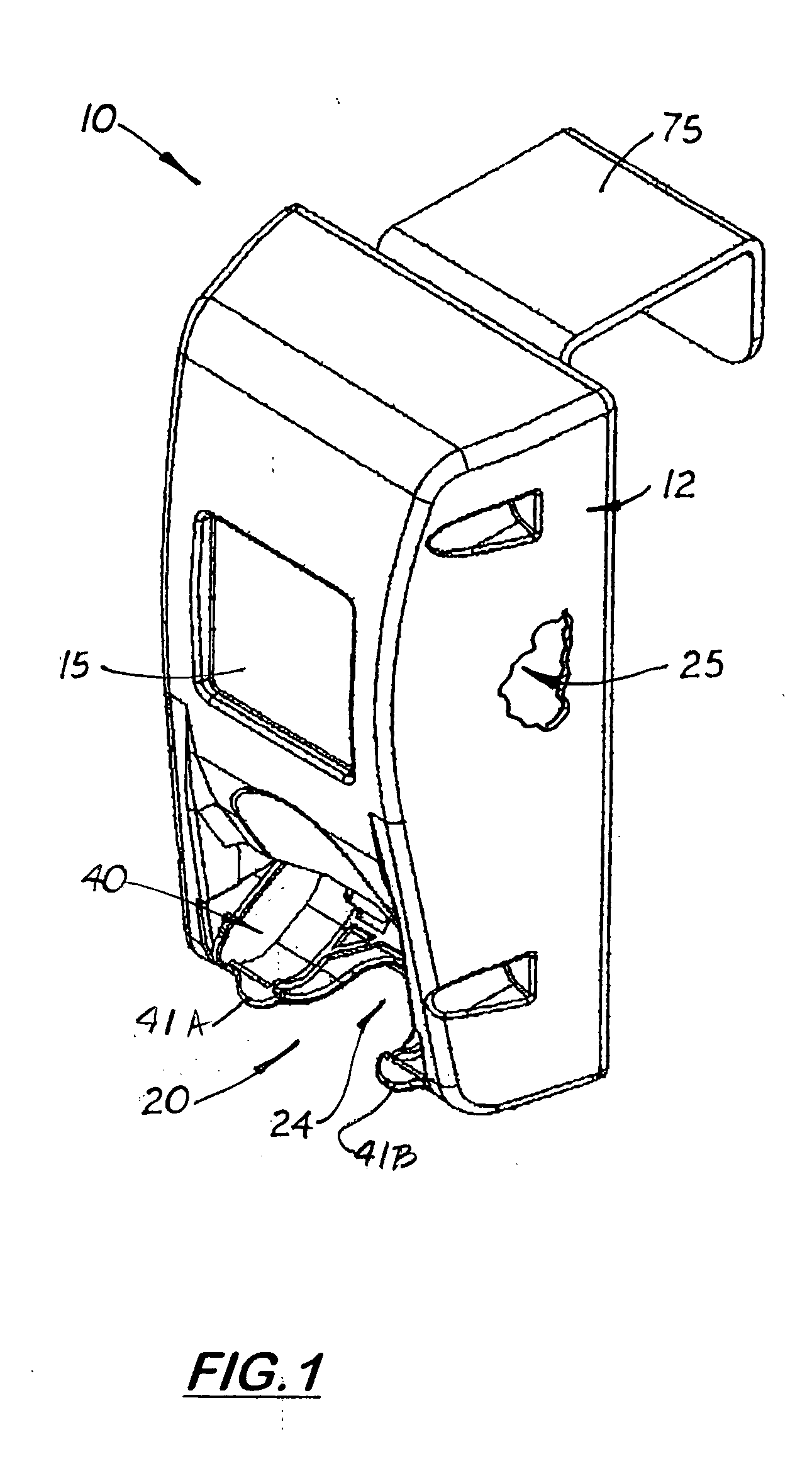
[0026] Referring the Figs., there is shown a shotgun shell dispenser 10 used to carrier a plurality of shot gun shells 90 specially designed to allow a hunter to easily remove and load individual shells 90 into the dispenser 10 using the fingers on one hand. The dispenser 10 is also specifically designed to allow the hunter to pre-pack multiple dispensers 10 and then stack them in an organized manner inside a box or suitable container.

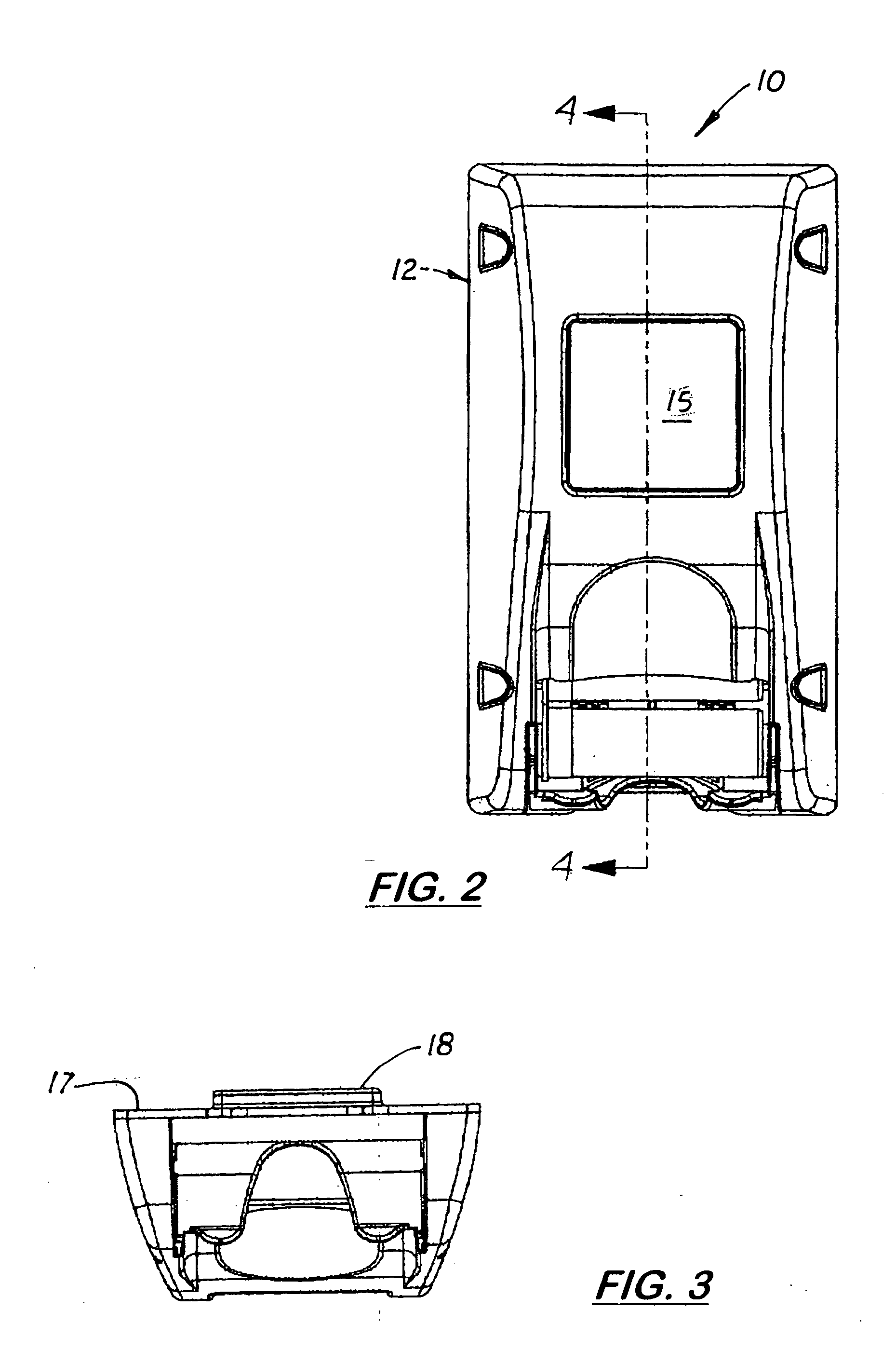
[0027] The dispenser 10 includes a rectangular-shaped, six-sided housing 12 with a lower loading and discharge opening 20. Located on the lower end wall of the housing 12 adjacent to the lower loading and discharge opening 20 is a pivoting ball 40 with a u-shaped finger cutout 24 formed thereon that allows the hunter to extend his or her middle finger around a shell 90 disposed on the bail 40. The housing 12 includes a hollow cavity 25 designed to hold a row of stacked, transversely aligned shells 90. (See FIG. 5)

[0028] Located inside the hollow cav...


PUM


Abstract

A shotgun shell dispenser that includes a rectangular-shaped six-sided housing with a lower loading and discharge opening formed on one end. Formed on the lower sidewall of the housing adjacent to the lower discharge opening. Located inside the housing is a downward biased stomper plate designed to press against the upper most shell to constantly force the row of shells downward towards the discharge opening. Located inside the discharge opening is a pivoting bail designed to receive and temporarily hold one shell in a blocking position inside the discharge opening. The pivoting bail is biased inward to maintain the lower shell in a blocking position thereby prevent the other shells from being accidentally discharged. The bail includes two finger tabs and a u-shaped finger opening that allows the user to easily lift and rotate the bail to dispense the shell located thereon.

Description

[0001] This is a utility patent application, which claims benefit of U.S. Provisional Application No. 60 / 583,269 filed on Jun. 11, 2004.BACKGROUND OF THE INVENTION [0002] 1. Field of the Invention [0003] This invention relates to carriers for ammunition, and more particularly to carriers used to temporarily hold shotgun shells. [0004] 2. Description of the Related Art [0005] Carriers for shotgun shells that attached to the belt of a hunter are well known. (See U.S. Pat. Nos. 278,980; 2,075,988; 2,122,003; 2,756,913; 2,837,258; and 3,219,244). Ideally, such carriers should allow the hunter to easily load a box of shotgun shells, securely hold the shells while hunting, and then allow the hunter to easily remove individual shells when needed. [0006] Some carriers include a dispensing mechanism that facilitates the removal of individual shells from the carrier. Unfortunately, the dispensing mechanisms require the hunter to use both hands to refill the carrier. In order to refill the car...

Claims


Application Information

Patent Timeline
Patent Type & Authority Applications(United States)
IPC IPC(8): F41A15/00
CPCF42B39/002
Inventor ROGERS, PAUL
Owner ROGERS PAUL
Why Eureka
Try Eureka