Unlock instant, AI-driven research and patent intelligence for your innovation.

Oscillator circuit for a sensor

Active Publication Date: 2006-01-19
IMF ELECTRONIC GMBH
View PDF1 Cites 8 Cited by
  • Summary
  • Abstract
  • Description
  • Claims
  • Application Information

AI Technical Summary

Benefits of technology

[0013] Another advantage of the oscillator circuit according to the invention is that the electrical oscillation of the tuned circuit, in contrast to the examples known from the prior art, cannot be suppressed by such high attenuation either. This results in that each influence state of the oscillator circuit can be recognized using the electrical oscillation of the tuned ci

Problems solved by technology

The attenuation of the tuned circuit in the simple oscillator circuit under discussion here leads to the electrical oscillation of the tuned circuit coming completely to a standstill.
The described eddy current losses reduce the total gain of the oscillator circuit, by which, ultimately for the case in which the conductive article is in the influence area of the electromagnetic stray field, the oscillation condition for the tuned circuit is no longer satisfied, and therefore, the electrical oscillation comes to a standstill.
One disadvantage is the inevitable chopping of the electrical oscillation of the oscillator circuit.
Since oscillators require a certain build-up time in order to shift from a nonoscillating state into an oscillating state, such a sensor or the electrical oscillation of the oscillator circuit used in it is not suited for communicating its actual influence state at any time.
Therefore, the sensors cannot be used correctly for a certain time; this especially means a considerable limitation for the serviceability of such an inductive sensor when, for example, high-speed movements of articles, for example, in a counting process, must be recognized.

Method used


Image

  • Oscillator circuit for a sensor
  • Oscillator circuit for a sensor
  • Oscillator circuit for a sensor

Examples


Embodiment Construction

[0024] The oscillator circuit in accordance with the invention is described below using a preferred embodiment of an inductive sensor. The invention could also be equally well described using any other sensor circuit, such as, for example, using a capacitive sensor which requires the use of an oscillator circuit. Therefore, quite generally, the sole prerequisite for implementation of the invention is simply the necessity of using an oscillator circuit regardless of the purpose which it fulfills in the higher-order circuit.

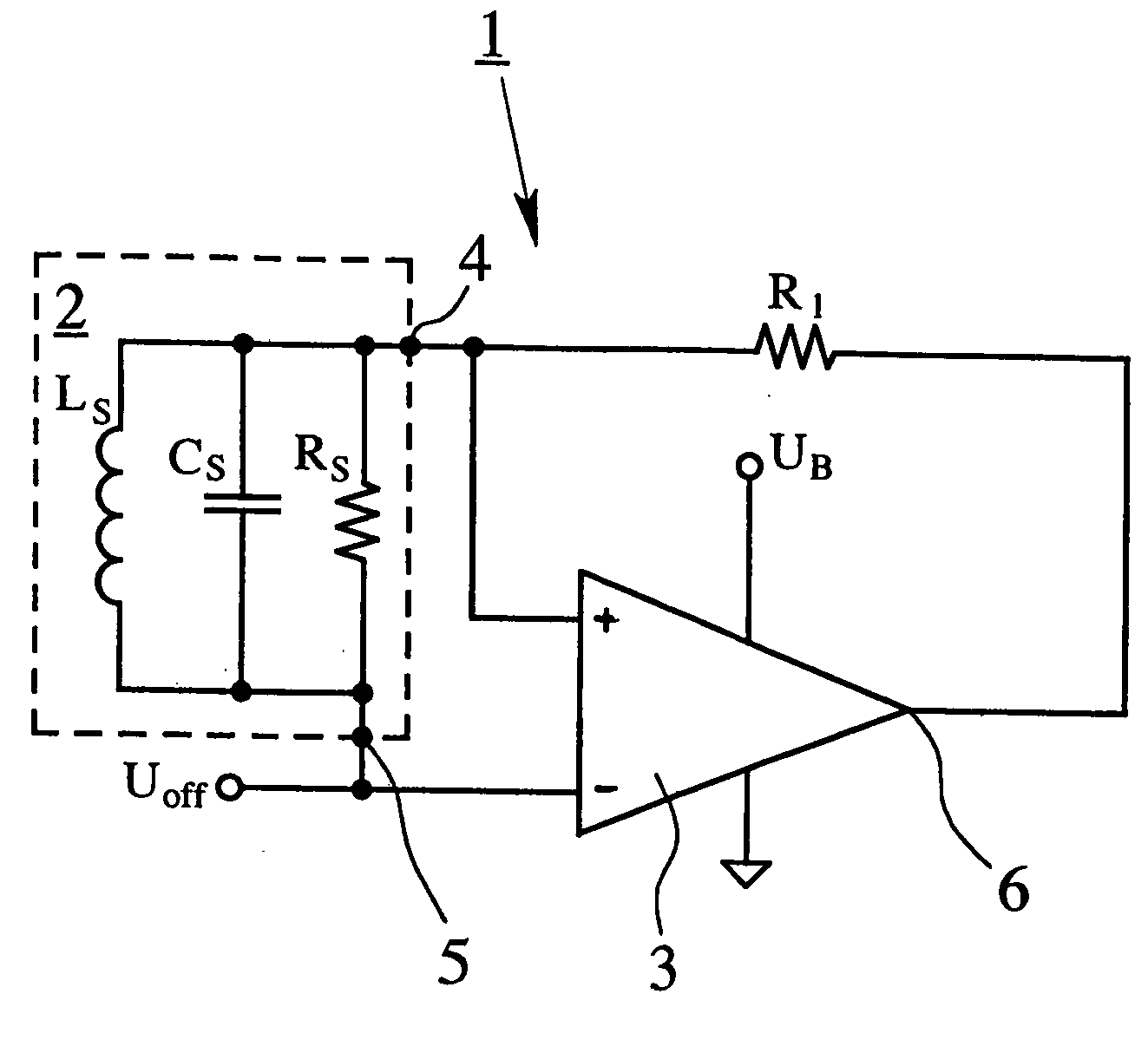
[0025]FIG. 5 shows an oscillator circuit 1 which is known from the prior art and upon which the present invention is based. The oscillator circuit 1 comprises a tuned circuit 2 and an operational amplifier 3. The tuned circuit 2, in this case, is made as a harmonic parallel tuned circuit with a capacitor with a capacitance CS, a coil with an inductance LS and a resistor R8. The first terminal 4 of the tuned circuit 2 is connected to the noninverting input of the o...


PUM


Abstract

An oscillator circuit for a sensor, with a tuned circuit (2) and an operational amplifier (3), the electrical oscillation of the tuned circuit (2) is capable of being tapped between a first terminal (4) and a second terminal (5) of the tuned circuit (2), and the first terminal (4) of the tuned circuit (2) being connected to the noninverting input of the operational amplifier (3) and the output (6) of the operational amplifier (3) is fed back to the noninverting input of the operational amplifier. The oscillator circuit is designed to improve the dynamic behavior of the oscillator circuit by the second terminal (5) of the tuned circuit (2)—at least in terms of AC voltage—being directly connected to the inverting input of the operational amplifier (3).

Description

BACKGROUND OF THE INVENTION [0001] 1. Field of Invention [0002] The invention relates to an oscillator circuit for a sensor, with a tuned circuit and an operational amplifier, the electrical oscillation of the tuned circuit capable of being tapped between a first terminal and a second terminal of the tuned circuit and the first terminal of the tuned circuit being connected to the noninverting input of the operational amplifier and the output of the operational amplifier being fed back to the noninverting input of the operational amplifier. [0003] 2. Description of Related Art [0004] Oscillator circuits of the type under consideration here have long been known in different embodiments and are used in circuit engineering wherever electrical oscillations (generally periodic characteristics of electrical voltages) are used, and for example, they are used as clocks for a circuit as a carrier of information or as periodic test signals. [0005] One common application for these oscillator ci...

Claims


Application Information

Patent Timeline
IPC IPC(8): H03L7/00
CPCH03K17/9547
Inventor SAUTER, MELNRADLAMARCHE, JEAN-LUC
Owner IMF ELECTRONIC GMBH