Image forming apparatus and paper ejection method of image forming apparatus

a technology of paper ejection and image forming apparatus, which is applied in the direction of electrographic process apparatus, instruments, optics, etc., can solve the problems of jamming of paper sheets, paper sheets cannot be stiffened, and the rear end of some paper sheets may be left behind, so as to improve the good conveying of paper sheets

Active Publication Date: 2006-01-19
KK TOSHIBA +1
View PDF0 Cites 3 Cited by
  • Summary
  • Abstract
  • Description
  • Claims
  • Application Information

AI Technical Summary

Benefits of technology

[0009] Accordingly, an advantage of the present invention is to provide an image forming apparatus having an optional device and a paper ejection method thereof for improving the good conveying of sheets of paper in a paper ejection unit and even if ejecting the sheets of paper to an intra-body paper ejection unit, causing no paper jamming.
[0010] To achieve the above advantage, one aspect of the present invention is to provide an image forming apparatus comprising, an image forming portion to form a toner image on a recording media, a fixing unit to clamp and convey said recording media and fixing said toner image, an ejection unit installed on a downstream side of said fixing unit to eject said recording media, an intra-body paper ejection unit to stack said recording media ejected from said ejection unit, a relay unit to convey said recording media ejected from said ejection unit in an optional direction, and a drive unit to drive said ejection unit at a first rate when said ejection unit ejects said recording media toward said relay unit and to drive said ejection unit at a second rate faster than said first rate when said ejection unit ejects said recording media toward said intra-body paper ejection unit, after said recording media passes said fixing unit.

Problems solved by technology

Therefore the paper ejection rollers are generally set not to provide the corrugation function, when using an optional device.
However, in the image forming apparatus having the optional device, if it is intended to eject sheets of paper into the paper ejection unit on the apparatus body side, since the paper ejection rollers have no corrugation function, the sheets of paper cannot be stiffened and there is a fear that at the time of paper ejection, the rear end of some sheet of paper may be left at the position of the paper ejection rollers.
If the rear end of a preceding sheet of paper is left at the position of the paper ejection rollers like this, the succeeding sheet of paper is caught by the rear end of the preceding sheet of paper at the position of the paper ejection rollers, thus jamming of sheets of paper may be caused.
Therefore, for example, the paper ejection rate must be increased, when ejecting sheets of paper toward the intra-body paper ejection unit, though a problem arises that it cannot be applied to a paper ejection unit of an apparatus required to keep the paper ejection rate almost equal to the image forming rate, when ejecting sheets of paper toward the finisher which is an optional device.

Method used


Image

  • Image forming apparatus and paper ejection method of image forming apparatus
  • Image forming apparatus and paper ejection method of image forming apparatus
  • Image forming apparatus and paper ejection method of image forming apparatus

Examples


Embodiment Construction

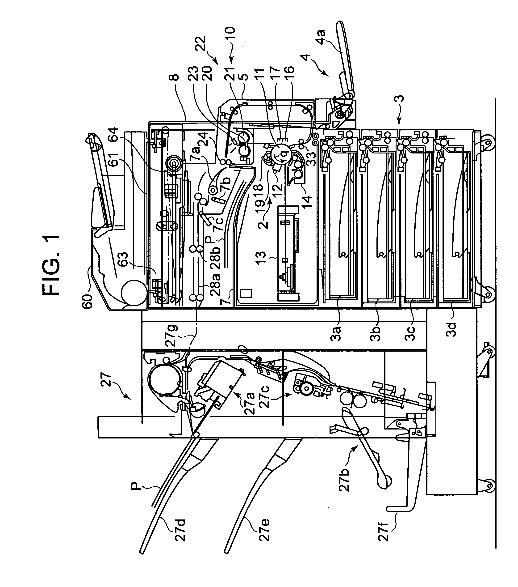
[0017] Hereinafter, the embodiment of the present invention will be explained in detail with reference to the accompanying drawings. FIG. 1 is a schematic block diagram showing a copier 10, which is an image forming apparatus of the embodiment of the present invention. The image forming rate of the copier 10 is set at ten and several sheets / min. to twenty and several sheets / min. Above an apparatus body 8 of the copier 10, a scanner 6 for reading document images is mounted. The scanner 6 has a platen glass 61 for setting documents supplied from an automatic document feeder 60, an optical unit 63 for irradiating light onto a document and focusing the reflected light from the document, and a CCD scanner unit 64 for reading the light from the optical unit 63.

[0018] Under the scanner 6 across an intra-body paper ejection unit 7 of the apparatus body 8, a photosensitive drum 11 and an image forming unit 2, which is an image forming portion are mounted. In the rotational direction of the ...


PUM


Abstract

A drive unit for changing the driving rate of paper ejection rollers for ejecting sheets of paper after fixing is installed, and an image forming apparatus has an option, and when ejecting the sheets of paper to an intra-body paper ejection unit, after the sheets of paper pass a fixing device, the paper ejection rate of paper ejection rollers 24 is increased, and the ejection force of the sheets of paper P is increased, and paper jamming at the time of paper ejection to the intra-body paper ejection unit is prevented.

Description

CROSSREFERENCE TO RELATED APPLICATION [0001] This application is based upon and claims the benefit of priority from prior Japanese Patent Application No. 2004-209006 filed on Jul. 15, 2004, the entire contents of which are incorporated herein by reference. FIELD OF THE INVENTION [0002] The present invention relates to an image forming apparatus and a paper ejection method of image forming apparatus for performing a finishing process for sheets of paper after fixing toner images. DESCRIPTION OF THE BACKGROUND [0003] As an image forming apparatus such as a copier and a printer, there is an apparatus such that the image forming rate is comparatively slow such as ten and several sheets / min. to twenty and several sheets / min. and sheets of paper after image forming are ejected into an intra-body paper ejection unit of the apparatus. In some image forming apparatus having such an image forming rate, to retain the paper ejection property into the paper ejection unit satisfactorily, the pape...

Claims


Application Information

Patent Timeline
Patent Type & Authority Applications(United States)
IPC IPC(8): G03G15/00
CPCG03G15/6573G03G2215/00827G03G2215/00426
Inventor SHISHIKURA, KENICHIRO
Owner KK TOSHIBA
Why Eureka
Try Eureka