Mounting method and mounting device

a mounting method and mounting device technology, applied in semiconductor/solid-state device testing/measurement, semiconductor/solid-state device details, instruments, etc., can solve the problems of large devices, long time, and increased costs, and achieve the effect of efficiently enclosing the bonding part, fast and easy achieving a predetermined vacuum degree, and satisfying various required treatment conditions

Inactive Publication Date: 2006-01-26
TORAY ENG CO LTD
View PDF11 Cites 21 Cited by
  • Summary
  • Abstract
  • Description
  • Claims
  • Application Information

AI Technical Summary

Benefits of technology

[0004] Accordingly, an object of the present invention is to provide a mounting method and a mounting device which can realize a local chamber structure capable of locally and efficiently enclosing a bonding part and its vicinity from surroundings and adequately varying the shape of the enclosed space interlockingly with the bonding operation while maintaining the enclosed condition even at the time of bonding, and which can quickly and easily achieving a predetermined vacuum degree or specified-gas atmosphere by a small device using the local chamber structure, thereby easily and inexpensively satisfying various required treatment conditions or mounting conditions.

Problems solved by technology

Therefore, the whole of the device including the chamber becomes a large-scale device, and there is a problem that the device becomes large and the cost thereof increases.
Further, because the inside volume of the chamber also increases, it takes a long time to reduce the pressure down to a predetermined vacuum degree or to replace the atmosphere with a specified gas, and there is a case where it is difficult to achieve a high vacuum-degree condition.

Method used


Image

  • Mounting method and mounting device
  • Mounting method and mounting device
  • Mounting method and mounting device

Examples


Embodiment Construction

[0028] Hereinafter, desirable embodiments of the present invention will be explained referring to figures.

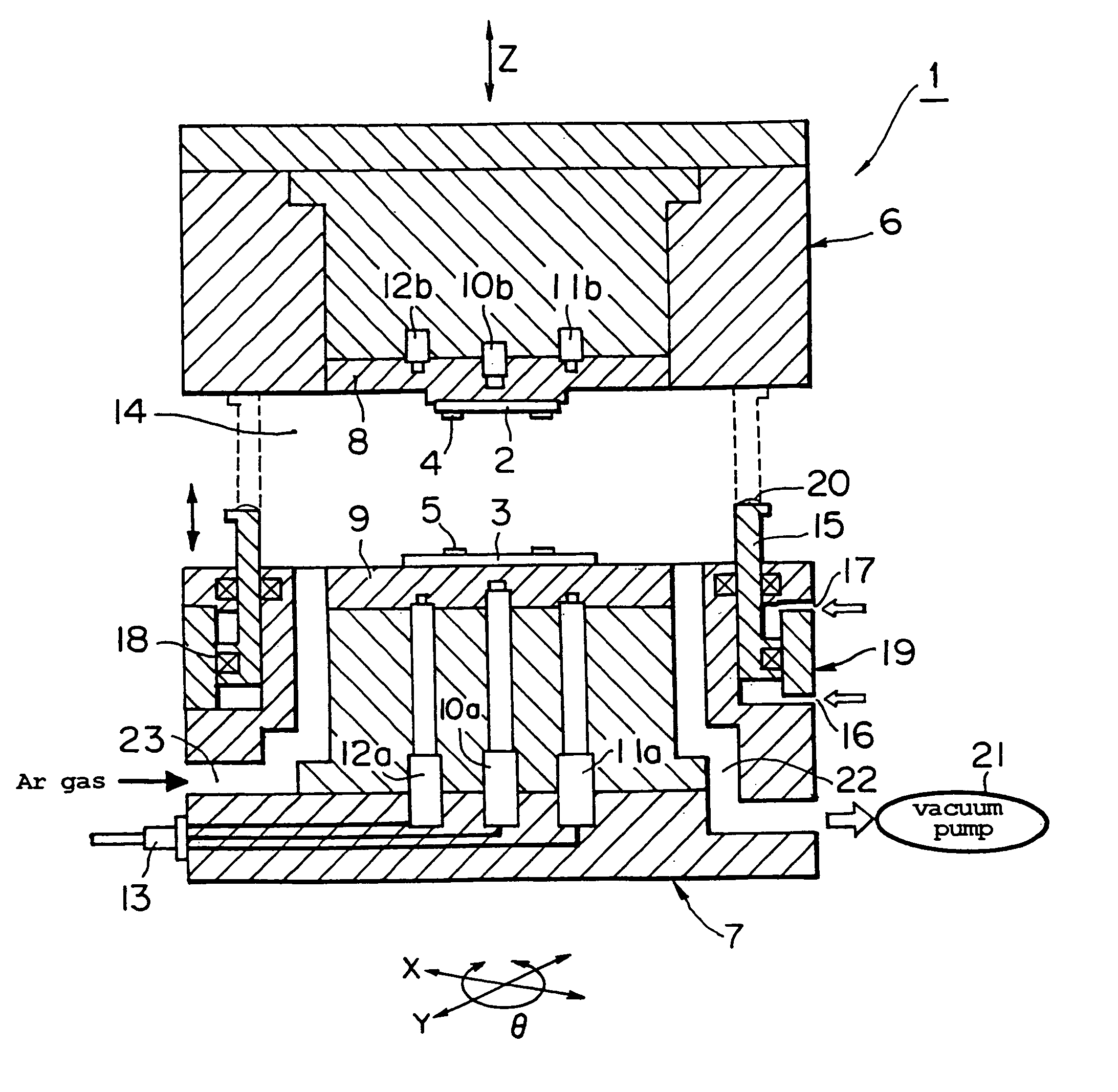
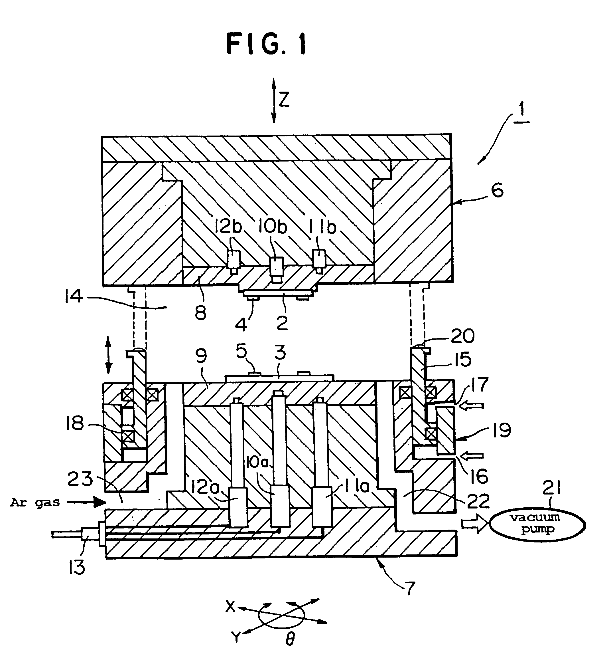
[0029] FIG. I shows a mounting device 1 according to an embodiment of the present invention. In FIG. 1, as objects facing each other with a gap, a case is exemplified where one object is a chip 2 and the other object is a substrate 3. A plurality of bumps 4 (in FIG. 1, two bumps 4 are shown) are provided on chip 2, and corresponding pads 5 (for example, electrodes) are provided on substrate 3. Chip 2 is held by a chip holding means 6 provided as one object holding means, and substrate 3 is held by a substrate holding means 7 provided as the other object holding means. In this embodiment, chip holding means 6 can be adjusted in position in Z direction (in a vertical direction), and substrate holding means 7 can be adjusted in position in X, Y directions (a horizontal direction) and / or in a rotational direction (θ direction).

[0030] Where, chip 2 means any object with any form be...


PUM

PropertyMeasurementUnit
pressureaaaaaaaaaa
volumeaaaaaaaaaa
vacuumaaaaaaaaaa

Abstract

A mounting method and a mounting device, the mounting method comprising the steps of, after positioning objects being bonded relative to each other, moving a movable wall positioned therearound until coming into contact with one object holding means to form a local chamber having a local enclosed space, enclosing both objects in the chamber, reducing the pressure in the chamber, moving the object holding means in a direction for reducing the volume of the chamber and moving the movable wall following the movement of the object holding means, and bonding both objects to each other by pressing, whereby, since the part to be bonded and its vicinity can be locally and efficiently enclosed separably from surroundings, and the local chamber capable of properly varying the shape of the enclosed space can be formed interlockingly with the bonding operation while maintaining the enclosed state even at the time of bonding, a specified mounting can be easily performed by a small device.

Description

TECHNICAL FIELD OF THE INVENTION [0001] The present invention relates to a mounting method and a mounting device for bonding objects such as chips or substrates to each other, and specifically to a method and a device for forming a local chamber structure having a movable wall for locally enclosing a bonding part from surroundings and carrying out mounting. BACKGROUND ART OF THE INVENTION [0002] Bonding objects to each other, for example, a mounting method for approaching a chip to a substrate at a condition of face down and bonding both objects to each other by pressing electrodes of the chip and the substrate to each other (as needed, accompanying with heating) is well known. Further, a method is also well known wherein, at the time of such a mounting, the mounting part is enclosed by surrounding it by a chamber, after the inside of the chamber is set at a specified atmosphere and various treatments are carried out, or after the pressure in the chamber is reduced and the inside of...

Claims


Application Information

Patent Timeline
Patent Type & Authority Applications(United States)
IPC IPC(8): B29C65/00B32B37/00B32B38/00H05H1/46H01L21/00H01L21/3065H01L21/60
CPCH01L21/67092H01L24/75H01L2924/07802H01L2924/07811H01L2924/014H01L24/81H01L2224/16H01L2224/75H01L2224/75743H01L2224/81203H01L2224/81801H01L2924/01004H01L2924/01033H01L2924/01057H01L2924/01078H01L2924/14H01L2924/01006H01L2924/0105H01L2924/00H01L2224/05573H01L2224/05568H01L2224/056H01L2924/00014H01L2224/0554H01L2224/05599H01L2224/0555H01L2224/0556
Inventor YAMAUCHI, AKIRATERADA, KATSUMINARABA, SATORUHARE, TAKASHI
Owner TORAY ENG CO LTD
Why Eureka
Try Eureka