
Drag adjustment device for a dual-bearing reel

a dual-bearing, adjustment device technology, applied in the direction of reels, applications, fishing, etc., can solve the problems of lever operation and difficult operation of the drag adjustment lever, and achieve the effect of less prone to disturb the lever operation

Active Publication Date: 2006-01-26
SHIMANO INC
View PDF15 Cites 24 Cited by
  • Summary
  • Abstract
  • Description
  • Claims
  • Application Information

AI Technical Summary

Benefits of technology

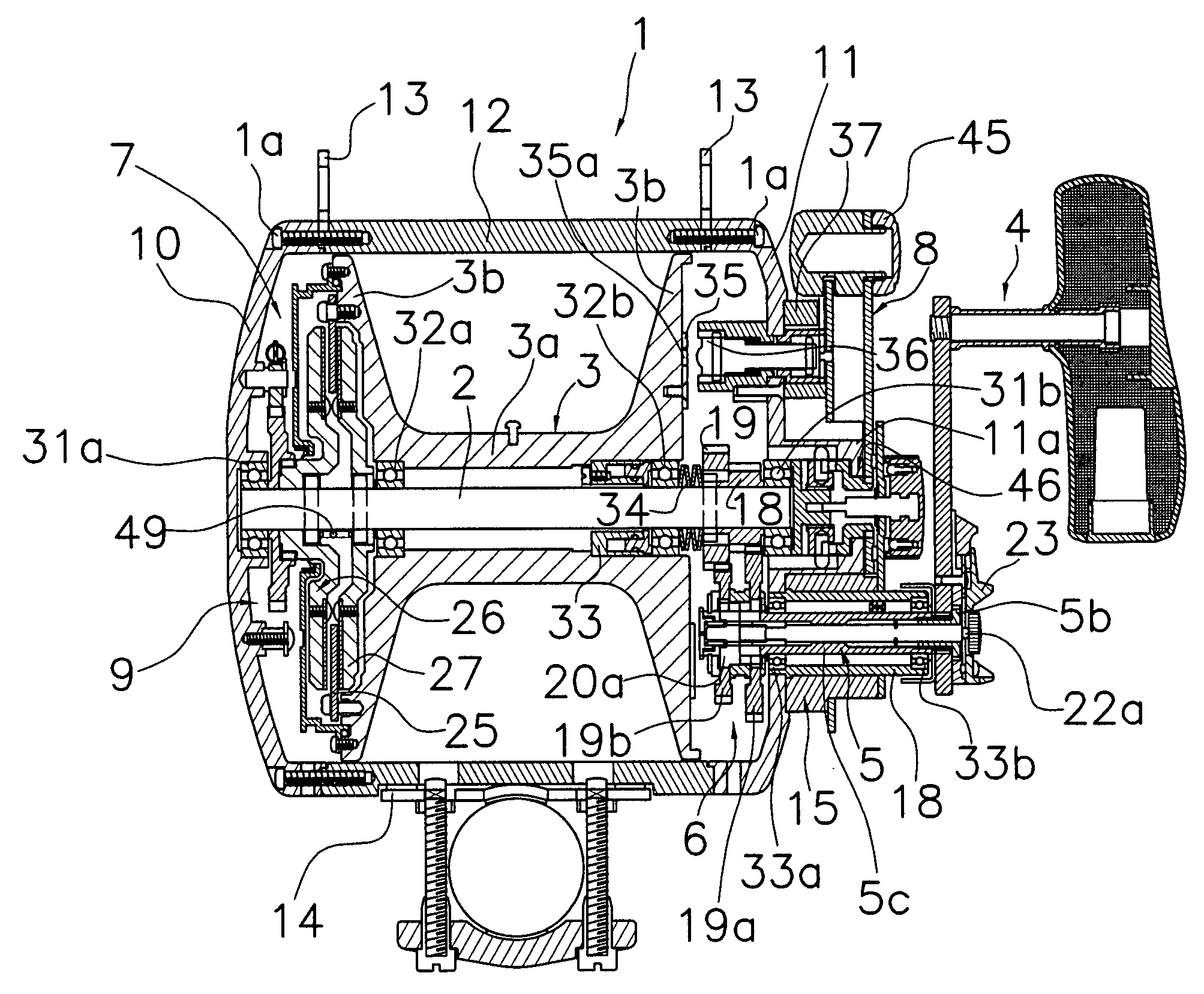
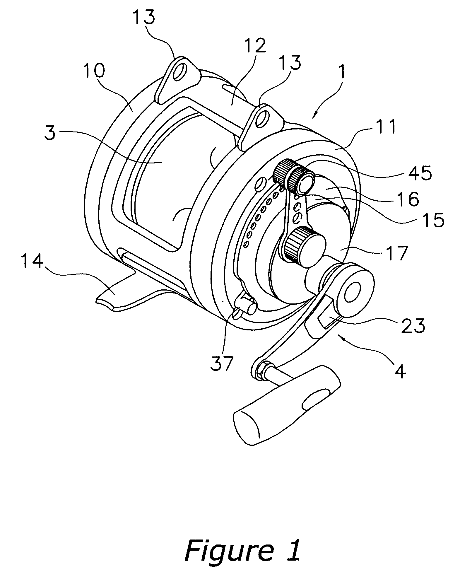
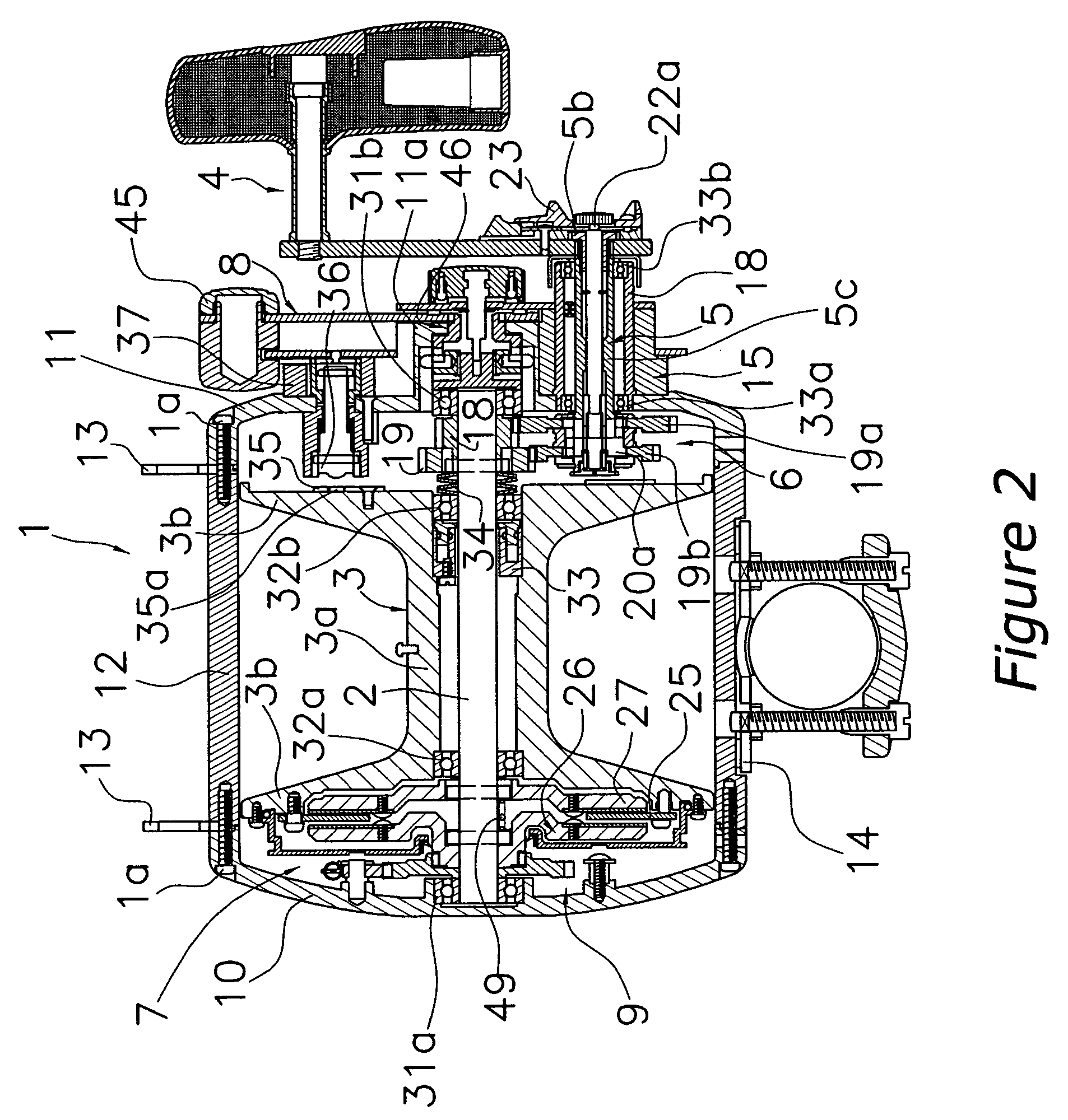
The present invention provides a drag adjustment device for a dual-bearing reel that reduces disturbances to lever operation and provides a clicking feeling without disturbing drag lever operation. The device includes a drag adjustment lever, an intermediate positioning mechanism, and a drag adjustment sounding mechanism. The drag adjustment lever can pivot between a free position and a maximum position, with the maximum position being the maximum drag position. The intermediate positioning mechanism allows the positioning block to contact the drag adjustment lever and be pressed inward or outward by the angler's finger or thumb. The drag adjustment sounding mechanism includes a plurality of sound-emitting recessed portions and a sound-emitting pin that can collide with the recessed portions to emit sound. The positioning block can retreat by pressing the drag adjustment lever, and the device includes a moving mechanism for moving the spool in the axial direction. These features improve the user experience and make the device more efficient and responsive.

Problems solved by technology

This disturbs lever operation and causes difficult operation of the drag adjustment lever toward the maximum position.

Method used


Image

  • Drag adjustment device for a dual-bearing reel
  • Drag adjustment device for a dual-bearing reel
  • Drag adjustment device for a dual-bearing reel

Examples


Embodiment Construction

[0033] Selected embodiments of the present invention will now be explained with reference to the drawings. It will be apparent to those skilled in the art from this disclosure that the following description of one embodiment of the present invention is provided for illustration only and not for the purpose of limiting the invention as defined by the appended claims and their equivalents.

[0034] As used herein to describe the present invention, the following directional terms “forward, rearward, left, right, upward, downward, vertical, horizontal, above, below and transverse” as well as any other similar directional terms refer to those directions of a fishing rod equipped with the dual bearing reel in accordance with the present invention. Accordingly, these terms, as utilized to describe the present invention should be interpreted relative to a fishing rod equipped with the present invention from a viewpoint behind the fishing rod and the dual bearing reel.

[0035] Referring initial...


PUM


Abstract

A drag adjustment device for a dual-bearing reel that adjusts the drag force of a lever drag mechanism includes a drag adjustment lever, an intermediate positioning mechanism and a drag adjustment sounding mechanism. The drag adjustment lever is pivotably attached to the reel unit about a spool shaft between a free position corresponding to a drag free state and a maximum position corresponding to a maximum drag state of the lever drag mechanism. The intermediate positioning mechanism includes a positioning block that is attached to the reel unit at the intermediate position between the free position and the maximum position so as to be able to advance or retreat. The positioning block contacts the drag adjustment lever to position the drag adjustment lever at the intermediate position. The drag adjustment sounding mechanism sounds in response to the pivoting of the drag adjustment lever.

Description

CROSS-REFERENCE TO RELATED APPLICATIONS [0001] This application claims priority to Japanese Patent Application Nos. 2004-213155, 2004-243752 and 2004-359574. The entire disclosures of Japanese Patent Application Nos. 2004-213155, 2004-243752 and 2004-359574 are hereby incorporated herein by reference. BACKGROUND OF THE INVENTION [0002] 1. Field of the Invention [0003] The present invention generally relates to an adjustment device. More specifically, the present invention relates to a drag adjustment device for a dual-bearing reel that adjusts the drag force of a lever drag mechanism to apply a braking force to a spool in the dual-bearing reel. [0004] 2. Background Information [0005] Generally, a dual-bearing reel is furnished with a drag mechanism which brakes the rotation of a spool in the line releasing direction. Among drag mechanisms, a lever drag mechanism has excellent operability and drag adjusting accuracy in contrast with a star drag mechanism. Thus, the lever drag mechani...

Claims


Application Information

Patent Timeline
Patent Type & Authority Applications(United States)
IPC IPC(8): A01K89/02
CPCA01K89/006A01K89/033A01K89/015
Inventor HIRAYAMA, HIROKAZUIWABUCHI, MASAKAZU
Owner SHIMANO INC
Learn More