Front access punch down patch panel

a patch panel and front access technology, applied in the field of patch panels, can solve the problems of affecting the installation process, and affecting the installation process, and achieving the effect of reducing the difficulty of installation and removal of cables, and reducing the difficulty of installation and removal

Inactive Publication Date: 2006-01-26
PANDUIT
View PDF16 Cites 185 Cited by
  • Summary
  • Abstract
  • Description
  • Claims
  • Application Information

AI Technical Summary

Problems solved by technology

The installer often encounters difficulties when removing or installing the cables because of the lack of access to the connections.
If the connections are only accessible in the back of the equipment rack system, the installer may not have sufficient room to access the connections.
Access from the front of the rack, however, may still be restricted by panels and cables positioned above or below the drawer in the equipment rack system.
As a result, there is still a need for full unobstructed front access to the communication connections mounted within the equipment rack systems.

Method used


Image

  • Front access punch down patch panel
  • Front access punch down patch panel
  • Front access punch down patch panel

Examples


Embodiment Construction

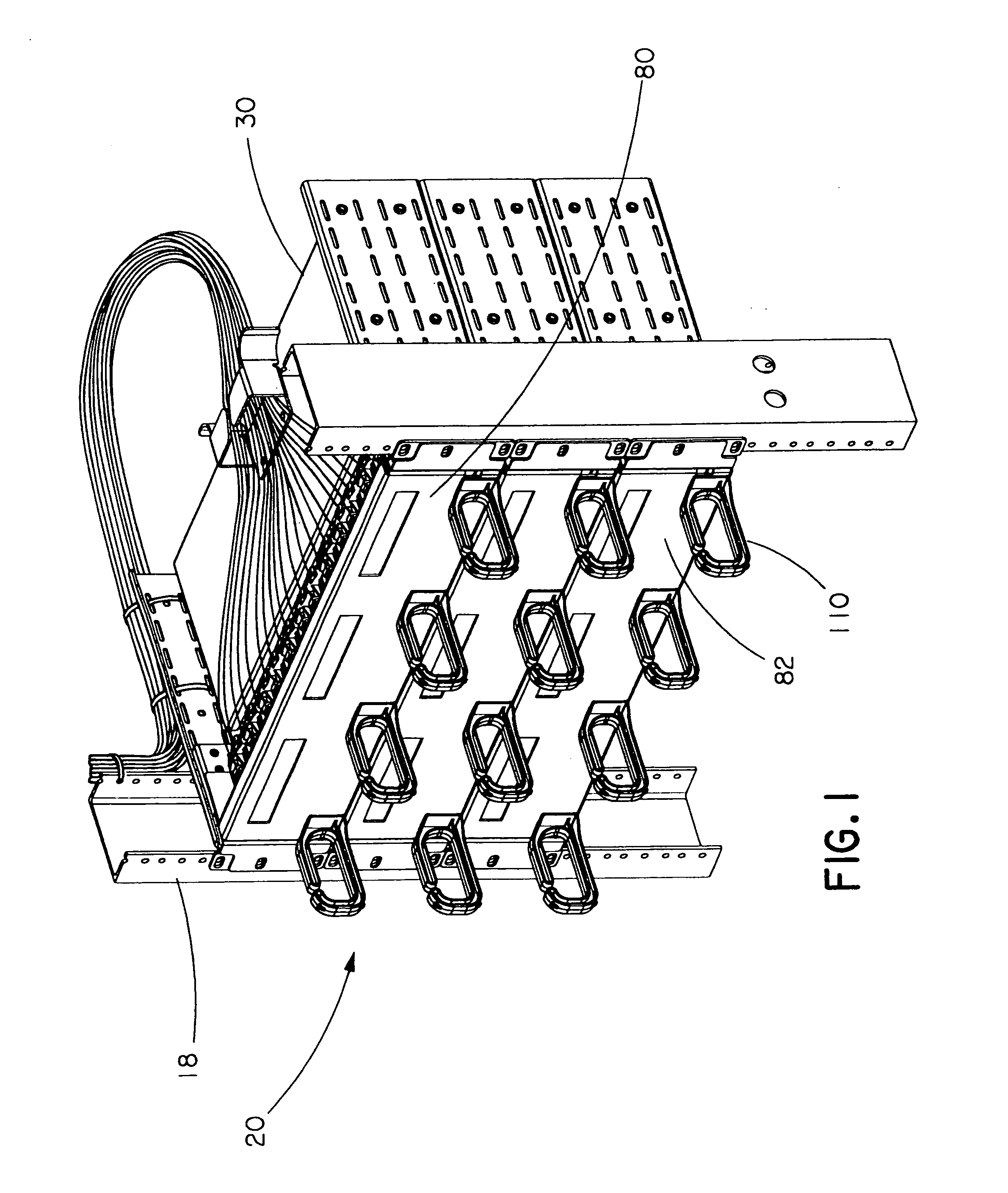
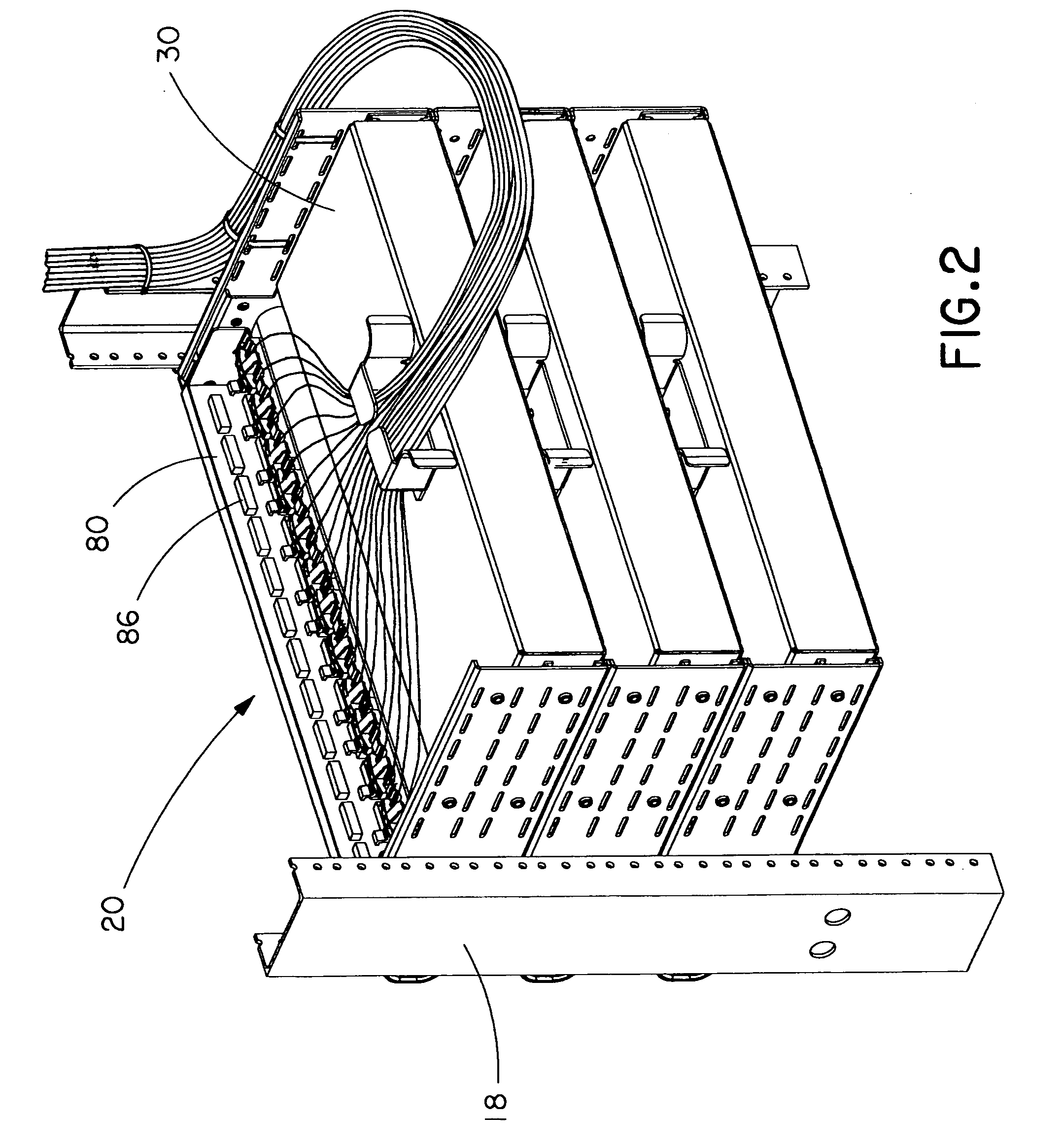
[0023]FIGS. 1 and 2 illustrate a plurality of punch down patch panel assemblies 20 of the present invention mounted to an equipment rack 18 or frame. The patch panel assemblies 20 may also be mounted in an equipment cabinet. Each patch panel assembly 20 has a plurality of cables that are connected to the patch panel 80 and routed along the equipment rack 18.

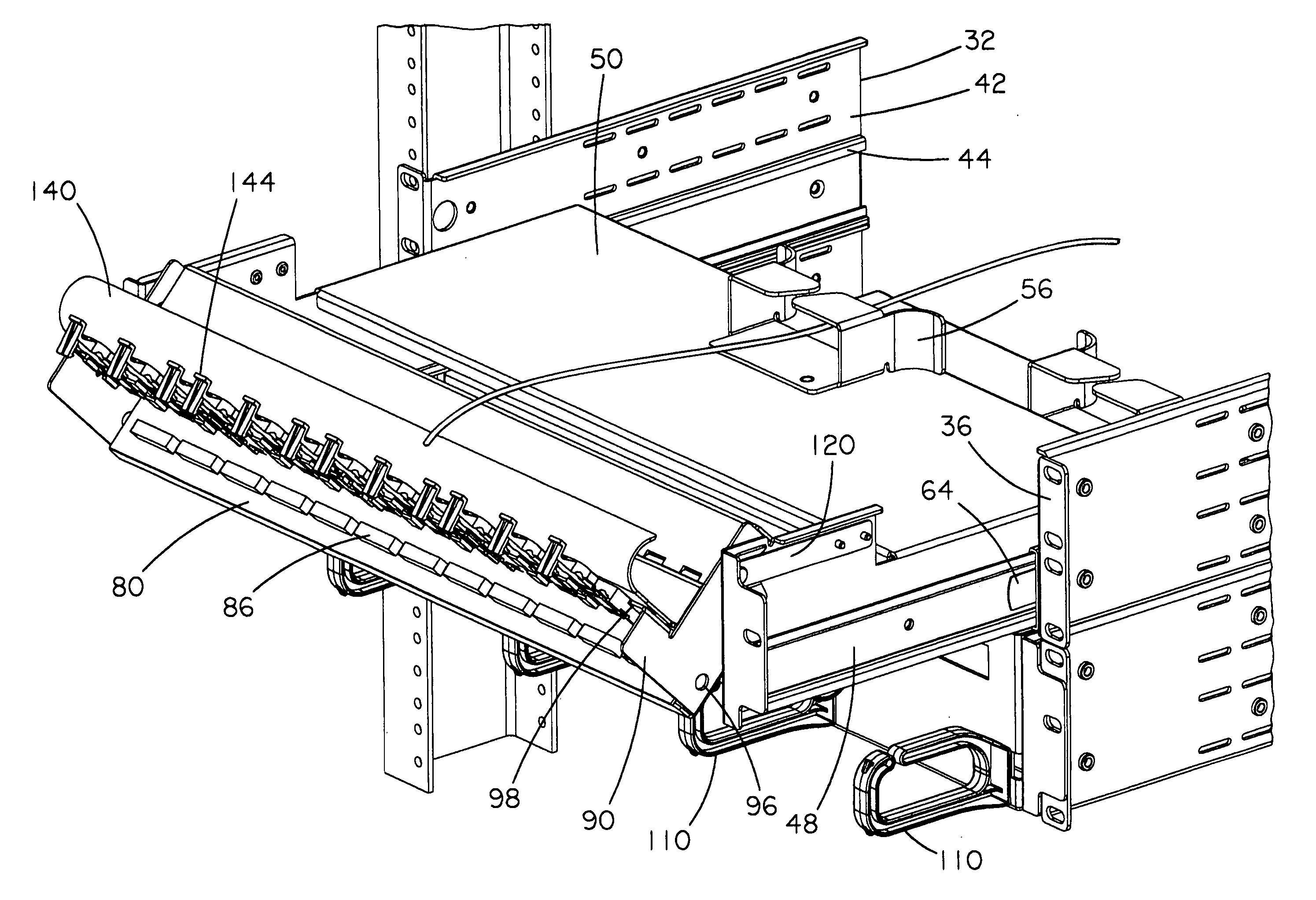
[0024] The patch panel assembly 20 includes a sliding drawer 30 with a patch panel 80 pivotally mounted to the drawer. The patch panel 80 includes a plurality of D-shaped cable management rings 110 attached to the front surface 82 of the patch panel 80. The patch panel 80 includes a plurality of modular jacks accessible from the front of the patch panel and a plurality of punch down connector blocks 86 accessible from the back of the patch panel.

[0025] As shown in FIG. 3, the sliding drawer 30 includes a pair of identical sidewalls 32 and a cable tray 34. Each sidewall 32 includes a mounting bracket 36 with a plurality of holes...


PUM


Abstract

The patch panel assembly includes a drawer and a patch panel pivotally mounted to the drawer. The drawer has a pair of sidewalls and a cable tray positioned therebetween. The cable tray has a plurality of slide locks including lock releases that allow the cable tray to move between a closed position and an open position with respect to the sidewalls. The cable tray also has a plurality of retainer clips that allow the patch panel to move between an upright position and a rotated position with respect to the cable tray.

Description

CROSS-REFERENCES TO RELATED APPLICATION [0001] This application claims priority to U.S. Provisional Application Ser. No. 60 / 590,220, filed Jul. 22, 2004, which is incorporated herein by reference.FIELD OF THE INVENTION [0002] The present invention relates to a patch panel for interconnecting communication cables and, more particularly, to a patch panel assembly that provides full access from the front of the patch panel for punch down terminations. BACKGROUND OF THE INVENTION [0003] In equipment rack systems used to distribute communication cables, it is necessary to provide access to the various connections for the removal or installation of the cables. The installer often encounters difficulties when removing or installing the cables because of the lack of access to the connections. If the connections are only accessible in the back of the equipment rack system, the installer may not have sufficient room to access the connections. Equipment rack systems have been designed with a d...

Claims


Application Information

Patent Timeline
Patent Type & Authority Applications(United States)
IPC IPC(8): G02B6/00H04L12/56
CPCG02B6/4455H04Q2201/02H04Q2201/08H04Q1/066H04Q1/064H04Q1/131H04Q1/023H04Q2201/10G02B6/4452G02B6/4453
Inventor CAVENEY, JACK E.WOJCIK, ALAN F.
Owner PANDUIT
Why Eureka
Try Eureka