Machine tool and method for computing attachment position of balancer in machine tool

a technology of machine tools and attachment positions, which is applied in the direction of manufacturing tools, instruments, mechanical apparatuses, etc., can solve the problems of rotary table vibration, workpieces becoming defective, and rotational imbalances on the rotary table, so as to achieve the effect of a suitable attachment position

Active Publication Date: 2006-01-26
YAMAZAKI MAZAK KK
View PDF14 Cites 34 Cited by
  • Summary
  • Abstract
  • Description
  • Claims
  • Application Information

AI Technical Summary

Benefits of technology

[0009] Accordingly, it is an objective of the present invention to easily achieve a suitable attachment position of a vibration suppressing balancer with respect to a rotary table.

Problems solved by technology

Depending on the attaching state of a workpiece or a jig on the rotary table, a rotational imbalance may be caused on the rotary table.
If such a rotational imbalance is caused, the rotary table vibrates.
When a turning process is performed in this state, the workpiece becomes defective.
In some cases, the rotary table might get broken, or the workpiece might be detached from the rotary table.
However, since informing the operator of the situation does not eliminate the rotational imbalance, the problem caused by the rotational imbalance is not fundamentally solved.
However, the technique disclosed in the above publication is for suppressing the speed fluctuation of the grinding head, and does not eliminate the rotational imbalance of the rotary tool.
Thus, even if the technique disclosed in the above publication is applied to the machine tool equipped with the rotary table, the rotational imbalance of the rotary table is not suppressed, and problems such as damage to the rotary table or detachment of the workpiece are not solved.

Method used


Image

  • Machine tool and method for computing attachment position of balancer in machine tool
  • Machine tool and method for computing attachment position of balancer in machine tool
  • Machine tool and method for computing attachment position of balancer in machine tool

Examples


first embodiment

[0040] the present invention will now be described with reference to FIGS. 1 to 18.

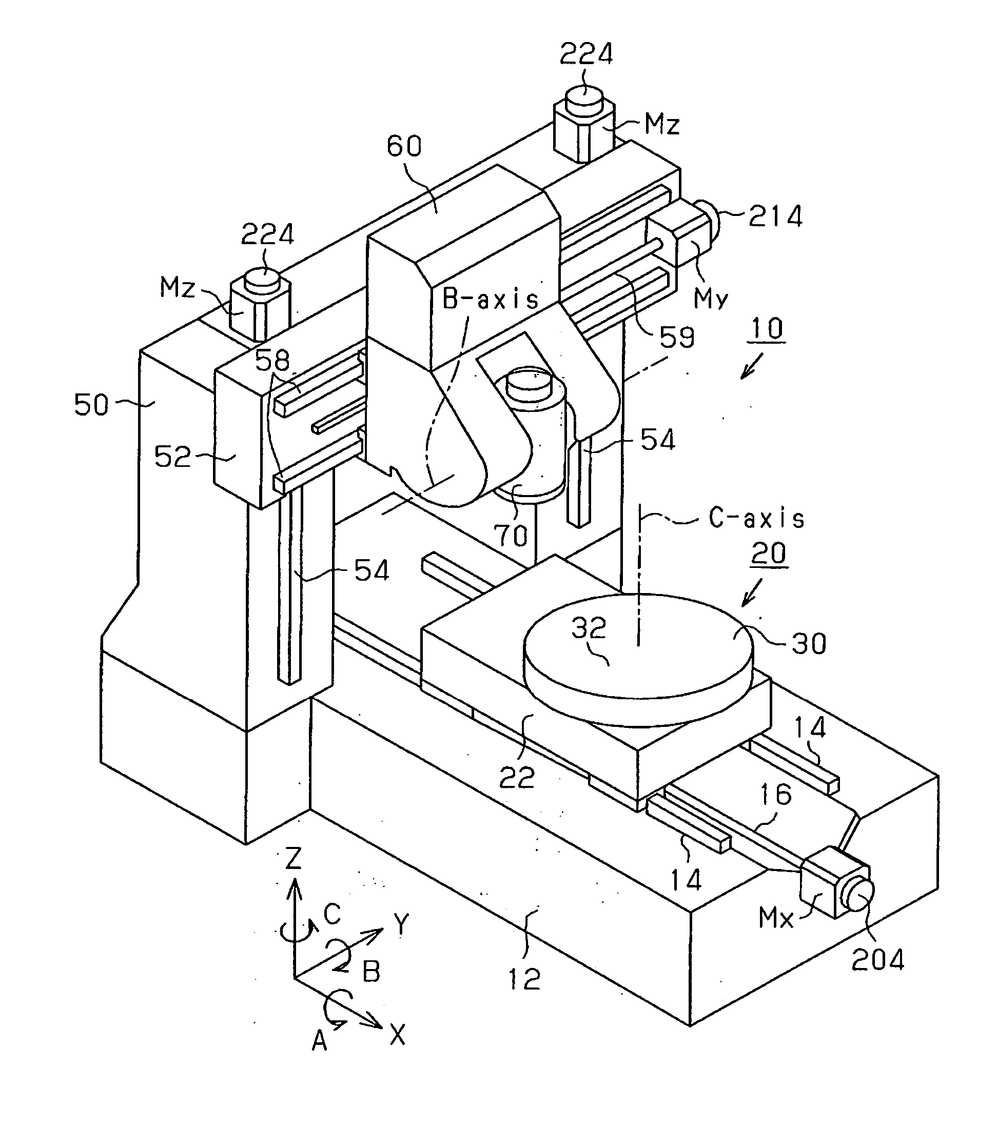
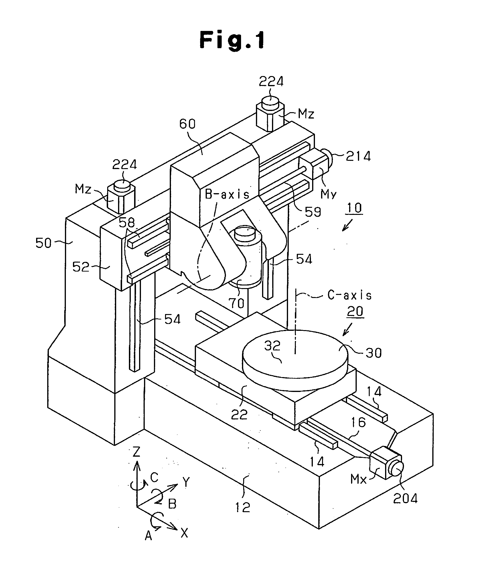
[0041] A multi-tasking machine 10 includes a bed 12 as shown in FIG. 1. Linear guide rails 14 (two in the drawing), which are parallel to each other, extend along an X-axis on the upper surface of the bed 12. A workpiece support apparatus 20 is provided on the linear guide rails 14. The workpiece support apparatus 20 includes a base 22. The base 22 is guided by the linear guide rails 14 and is movable along a predetermined moving direction, that is, the X-axis.

[0042] A nut 23 (see FIG. 4) is provided on the lower surface of the base 22, and the nut 23 is screwed to a ball screw 16 provided on the bed 12. The base 22 moves forward and backward or reciprocates along the X-axis as the ball screw 16 is selectively rotated forward and reverse by an X-axis drive motor Mx provided on the bed 12. The X-axis drive motor Mx functions as a movement device.

[0043] A disk-like rotary table 30 is provided on the b...

second embodiment

[0122] the present invention will now be described with reference to FIGS. 19 and 20 centered on the difference from the first embodiment.

[0123] The second embodiment differs from the first embodiment in the processes of steps S90 and S100 of FIG. 5, that is, the procedure for correcting the rotational imbalance of the rotary table 30.

[0124] In the first embodiment, the single balancer 40 is attached to the rotary table 30 to correct the rotational imbalance of the rotary table 30. In this case, the vibration of the rotary table 30 is suppressed to be within the permissible value, but the vibration cannot be made zero in theory. Furthermore, if the difference β between the ideal attachment angle (θ+π) of the balancer 40 and the arrangement angle αm closest to the ideal attachment angle (θ+π) does not satisfy the predetermined balance requirement (−π / 3<β<π / 3), the vibration cannot be suppressed.

[0125] Contrastingly, in the second embodiment, two balancers 40 are attached to the att...


PUM

PropertyMeasurementUnit
weightaaaaaaaaaa
displacement angleaaaaaaaaaa
angleaaaaaaaaaa

Abstract

When a rotary table rotates, a main control section of a multi-tasking machine detects vibration of the rotary table on which a workpiece is mounted based on fluctuation of a position droop computed by a servo system. The main control section computes the arrangement position (the eccentricity amount and the eccentricity angle) of the workpiece with respect to the rotary table based on, for example, the detected vibration, the weight of the workpiece, and the rotation speed of the rotary table. The main control section computes the attachment position of a balancer with respect to the rotary table based on the computed arrangement position of the workpiece. Therefore, a suitable attachment position of a vibration suppressing balancer with respect to the rotary table is easily obtained.

Description

RELATED APPLICATION [0001] This application claims priority to Japanese Patent Application 2004-217615, filed on Jul. 26, 2004, which is incorporated herein by reference. BACKGROUND OF THE INVENTION [0002] The present invention relates to a machine tool equipped with a rotary table, and to a method for computing the attachment position of a balancer with respect to the rotary table. [0003] A typical machine tool equipped with a rotary table is designed such that the rotary table is linearly moved forward and backward, and rotated. A workpiece attached to the rotary table is, for example, cut by a tool provided on a tool post. [0004] Depending on the attaching state of a workpiece or a jig on the rotary table, a rotational imbalance may be caused on the rotary table. If such a rotational imbalance is caused, the rotary table vibrates. When a turning process is performed in this state, the workpiece becomes defective. In some cases, the rotary table might get broken, or the workpiece ...

Claims


Application Information

Patent Timeline
Patent Type & Authority Applications(United States)
IPC IPC(8): B23C1/14B23Q11/00F16F15/32G01M1/38
CPCB23Q11/0035F16F15/22G01M1/16G01M1/32B23Q2220/004Y10T409/305656Y10T409/303752Y10T409/304312Y10T74/2109Y10T409/30476Y10T408/76Y10T409/307672Y10T409/307728
Inventor ICHINO, KENTAROYAMAMOTO, TOHRUSUZUKI, YASUHIKOOKADA, SATOSHIKURATA, MASAHIRO
Owner YAMAZAKI MAZAK KK
Why Eureka
Try Eureka