
Field labeled button

a button and label technology, applied in the field of buttons, can solve the problems of wear or fade, not easy to perform, and the identification method tends to not look aesthetically pleasing

Inactive Publication Date: 2006-01-26
LUTRON TECH CO LLC
View PDF6 Cites 34 Cited by
  • Summary
  • Abstract
  • Description
  • Claims
  • Application Information

AI Technical Summary

Problems solved by technology

These approaches suffer from obvious disadvantages in that the identifiers tend not to look aesthetically pleasing and can wear or fade over time.
Button engraving requires the manufacturer to engrave the appropriate identifier on the button before shipping the product, and is not easily performed in the field, that is, in the environment where the button is ultimately to be installed.
Also, typically only a limited number of “pre-made” identifiers are available from manufacturers.
Some manufacturers have provided ways for users and designers to request particular or custom identifiers to be engraved on buttons, but there is usually a large time period between the time when the identifier is requested and the time when the button or control with the identifier is shipped to the end user.

Method used


Image

  • Field labeled button
  • Field labeled button
  • Field labeled button

Examples


Embodiment Construction

[0020] As used herein, directional terms such as “upper”, “lower”, “top”, and “bottom”, as applied to a particular element refer to the orientation of that element as shown in a particular figure or figures being described, and are not meant to be limiting.

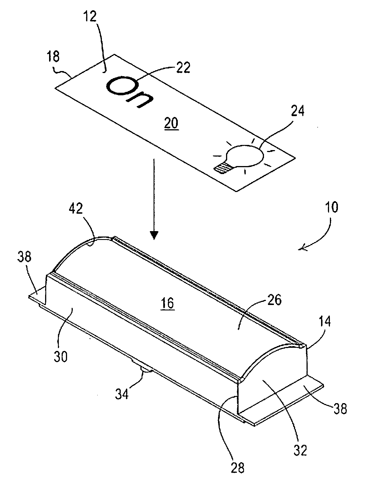
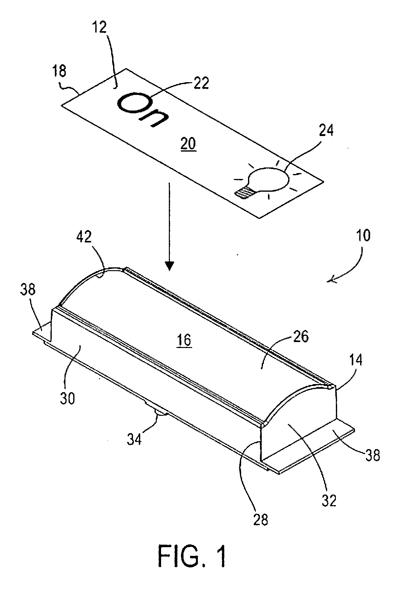
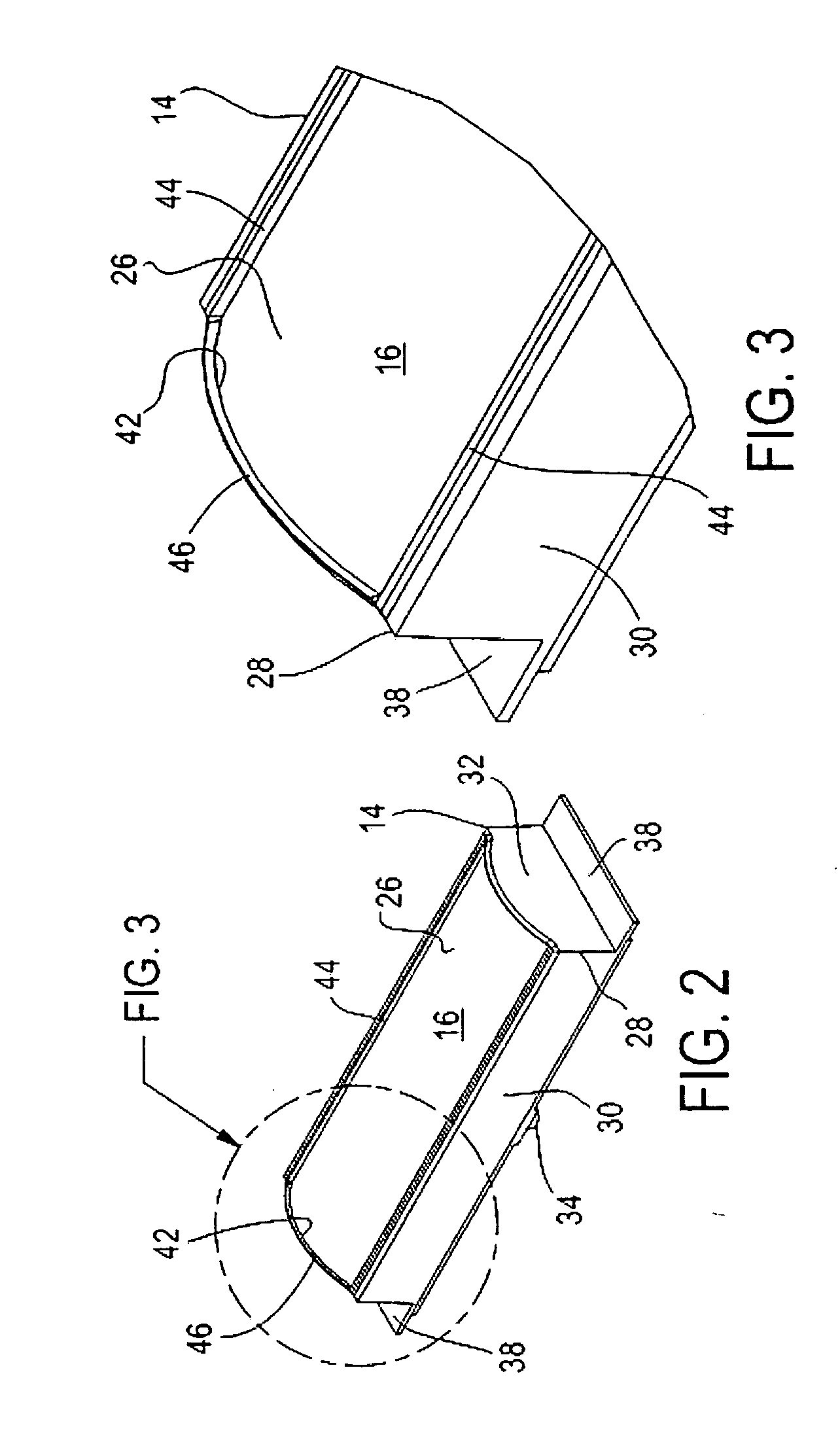
[0021] Referring to the drawings, where like numerals refer to like elements, there is shown in FIG. 1 a labeling system 10 according to an exemplary embodiment of the invention. The labeling system 10 is adapted to promote field-labeling of a button for a control system, such as at a location where the control system is being installed. Such field-labeling capability promotes flexibility and allows customization of button configuration and appearance at the field level, as opposed to button labeling provided at a manufacturer or distributor level. The labeling system 10 depicted in FIG. 1 is not limited to any particular application. Non-limiting exemplary applications include the labeling of buttons for control systems adapted ...


PUM

PropertyMeasurementUnit
lengthaaaaaaaaaa
lengthaaaaaaaaaa
depthaaaaaaaaaa

Abstract

A system for labeling a button in the field includes a label defining a peripheral boundary and a label-receiving surface defined by the button and adapted for receipt of the label. The label-receiving surface of the button defines a perimeter adapted to accommodate the peripheral boundary of the label. The button includes side and end portions defining raised edges or lips that define the label-receiving surface. The side and end portions serve to align the placement of the label on the label-receiving surface and also constrain lateral movement of the label. The side and end portions also protect the edges of the label against accidental dislodgement and peeling. The label typically has a suitable button identifier such as text, or a graphical design element such as an icon, printed thereon.

Description

CROSS-REFERENCE TO RELATED APPLICATION [0001] This application claims priority from U.S. provisional application No. 60 / 590,627, filed Jul. 23, 2004.FIELD OF THE INVENTION [0002] The present invention relates to buttons for lighting and window shading controls, and more particularly, to a system for labeling such buttons in the field. BACKGROUND OF THE INVENTION [0003] Conventional lighting and window shade controls include user-accessible buttons. The buttons allow users to control light levels and the positions of window shades, among other things. In order to identify the function to be performed by any particular button, it is desirable to affix an identifier to the button, or to the control adjacent the button. Preferably, the identifier is affixed to the button itself. [0004] The identifier may comprise an icon, a symbol, text, or some combination of the these elements. Ideally, the identifier will clearly indicate to a user the function or action that will be performed when t...

Claims


Application Information

Patent Timeline
Patent Type & Authority Applications(United States)
IPC IPC(8): B32B33/00
CPCG09F3/20G09F13/04Y10T428/14H01H2219/008H01H9/18
Inventor JACOBY, ELLIOT G.KRESCHOLLEK, BRAD M.SPIRA, JOEL S.
Owner LUTRON TECH CO LLC
Learn More