

Vapor deposition systems and methods
a technology of vapor deposition and vaporization, applied in the direction of dispersed particle separation, separation process, coating, etc., can solve the problems of clogging of ald system, difficult evacuation and purging of precursors in the deposition cycle, and complicated geometries such as showerheads
- Summary
- Abstract
- Description
- Claims
- Application Information
AI Technical Summary
Problems solved by technology
Method used
Image

Examples
Embodiment Construction
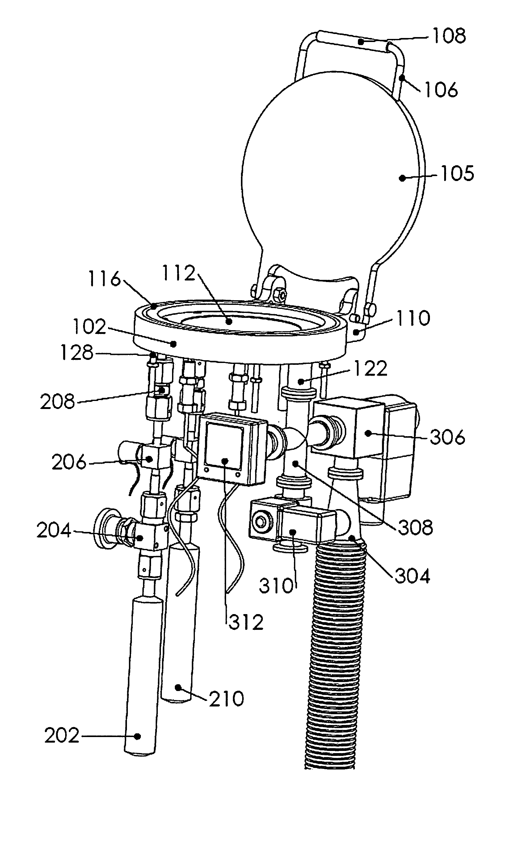
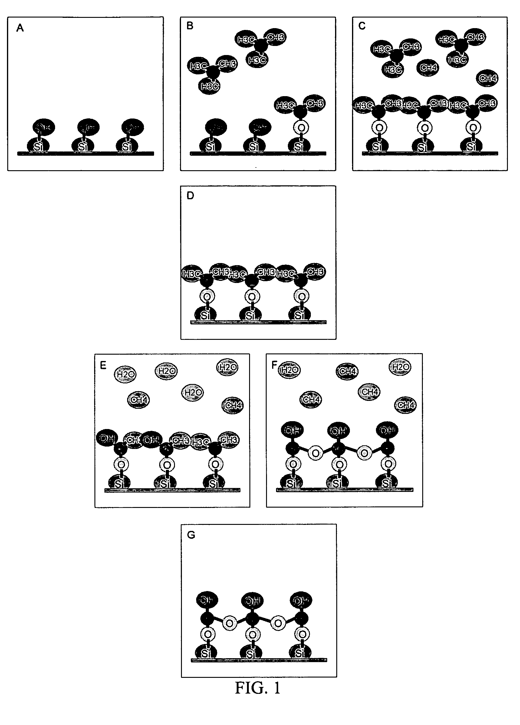
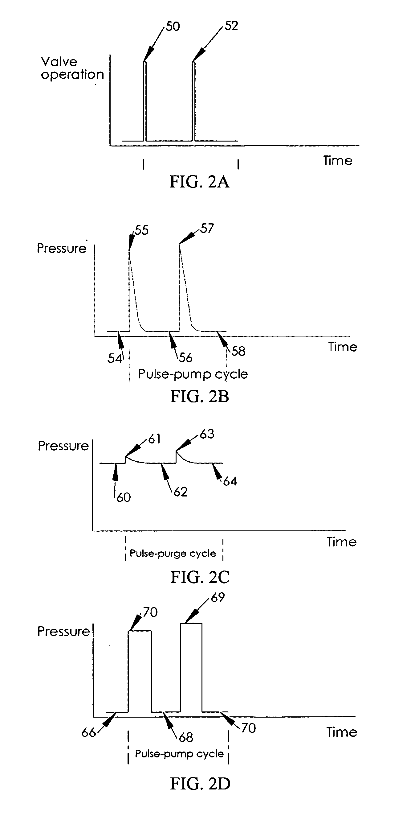
[0161] The invention provides atomic layer vapor deposition systems and methods associated with the same. The systems include a reaction chamber that enclose a substrate (or more than one substrate). Precursor (e.g., reactive species) supplies are connected to the reaction chamber through a port (or ports) to introduce suitable precursors into the chamber. In some cases, multiple precursor supplies are connected to a single precursor port; while, in other cases, each precursor supply may be connected to separate, respective ports. An outlet port may also be provided in the reaction chamber, for example, to remove gaseous species (e.g., unreacted precursor, reaction products, inert gas) at certain points during the process. The system includes an arrangement of heaters which provide suitable temperature conditions to promote a reaction between the precursors to deposit a material layer on the substrate. As described further below, the systems of the invention may be designed to inclu...
PUM
| Property | Measurement | Unit |
|---|---|---|
| temperature | aaaaa | aaaaa |
| temperature | aaaaa | aaaaa |
| temperature | aaaaa | aaaaa |
Abstract
Description
Claims
Application Information