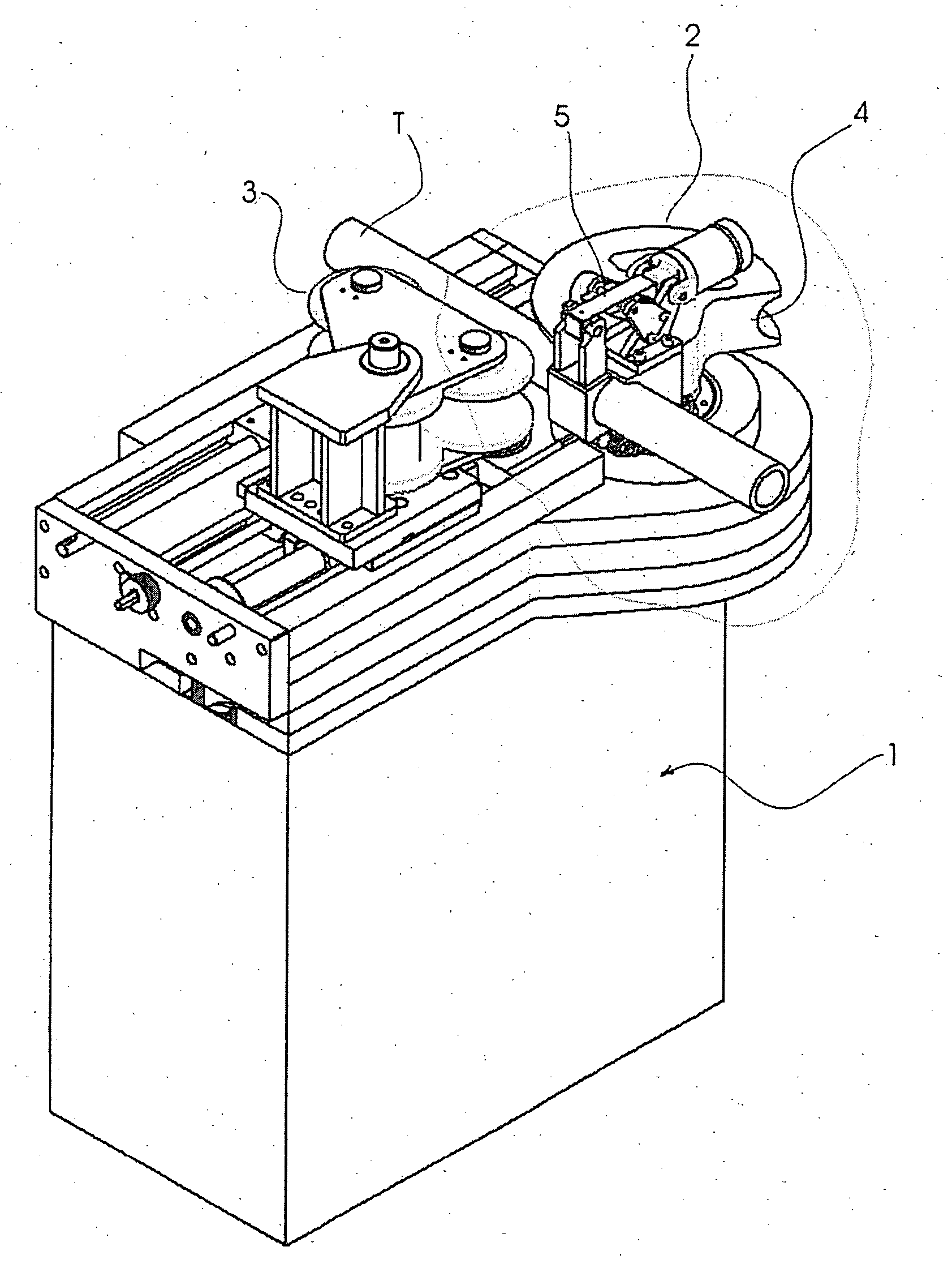
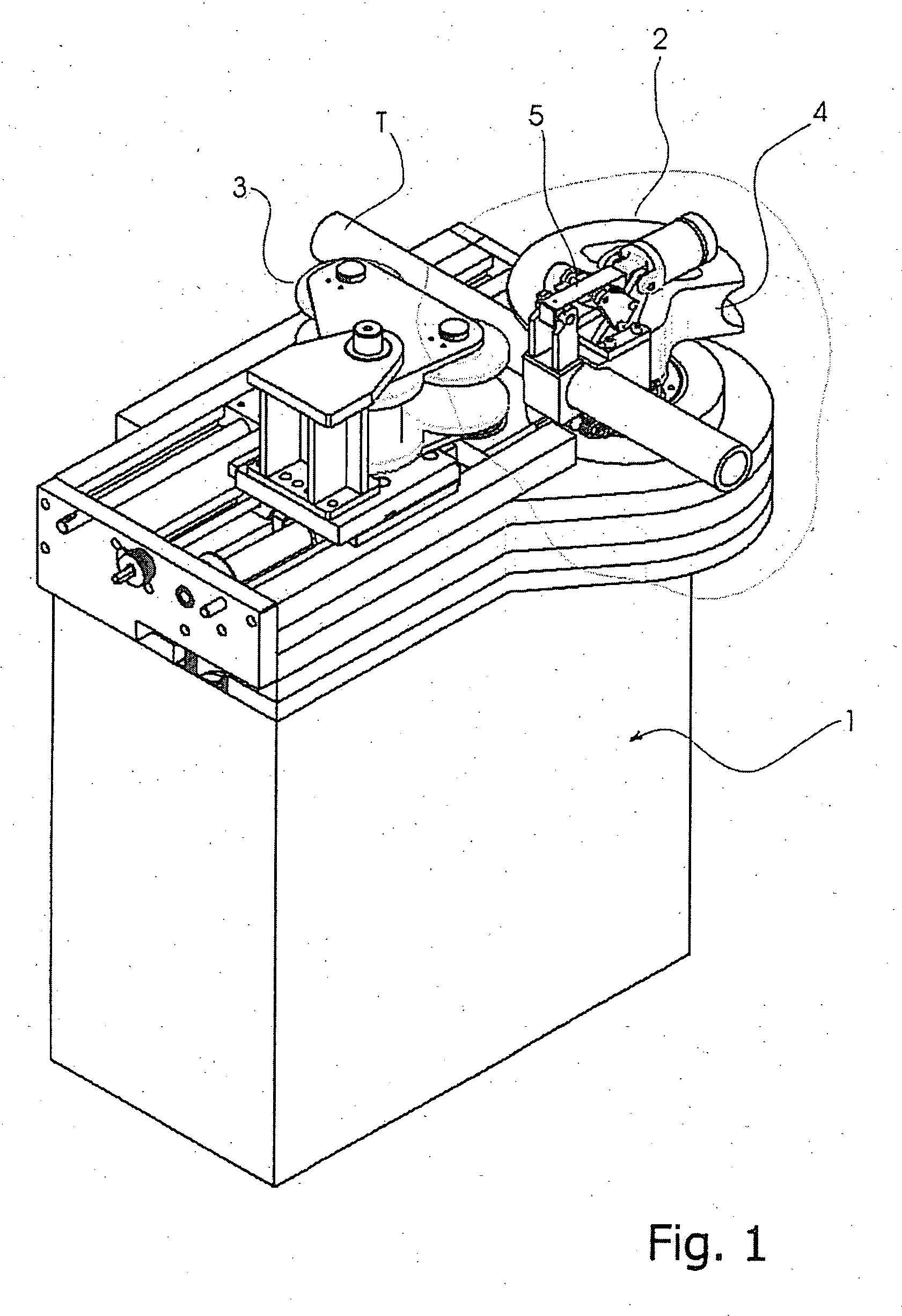
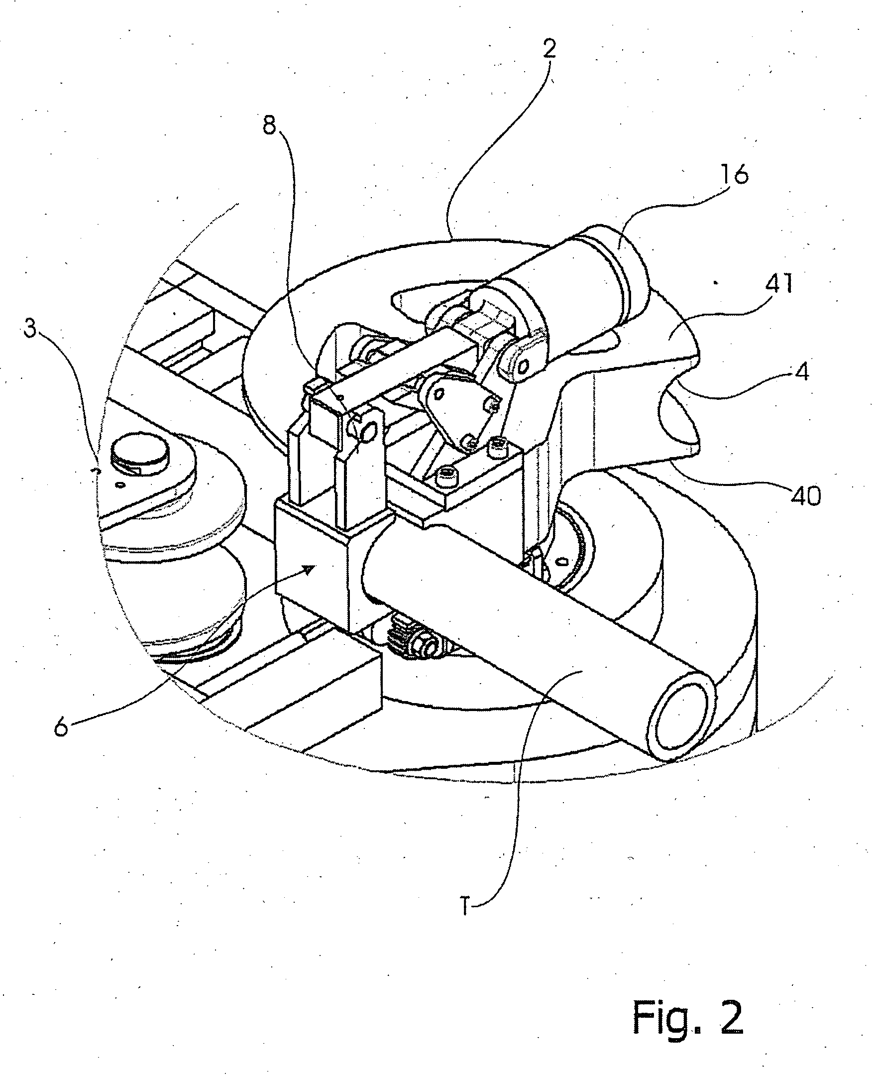
Bending machine die provided with a vise for clamping an elongated workpiece to be bent

a technology vise, which is applied in the field of bending machine die, can solve the problems of occupying a large spa

Inactive Publication Date: 2006-02-09
CML INTERNAT SPA
View PDF4 Cites 10 Cited by
  • Summary
  • Abstract
  • Description
  • Claims
  • Application Information

AI Technical Summary

Benefits of technology

[0008] In particular, an object of the invention is to assure a firm, reliable automatic clamping of an elongated workpiece to be bent against a die also for great tubes.

Problems solved by technology

Actually, the hydraulic cylinder chosen by Jesse Engineering is not small and occupies great space in the working zone of the bending machine.

Method used


Image

  • Bending machine die provided with a vise for clamping an elongated workpiece to be bent
  • Bending machine die provided with a vise for clamping an elongated workpiece to be bent
  • Bending machine die provided with a vise for clamping an elongated workpiece to be bent

Examples


second embodiment

[0034] In this second embodiment the pivoting axis X′ for swinging the hydraulic cylinder 29 comprises a pivot 30 passing through the cylinder rod 31 and engaging coaxial holes in sustaining means, indicated as 32, of the whole support 39.

[0035] A guiding means for the swinging hydraulic cylinder 29 includes a guide 33 symmetrically provided on both retaining elements 32 of the support. The guide 33 is in the form of an elongated slot.

[0036] Pivots 330, which are radially projecting from opposite parts of the cylinder 29, are slidable inside the guide 33. Analogously pins 34 engaging the retaining end 8 of the movable jaw 6 are made radially projecting from the hydraulic cylinder 29.

[0037] The second embodiment of the bending machine die is more advantageous than the first one as it is less cumbersome and equally effective with respect to the first one. With reference to FIGS. 7 to 9, particularly to FIG. 9, which is a perspective view, there is shown a first alternate of the mova...

second modified embodiment

[0042] Reference is made now to FIGS. 12 and 13, which are a side view and a front view respectively, of bending machine die according to the present invention. In this modified embodiment equal or similar parts, which are indicated by the same reference numerals as those of the embodiment depicted in FIGS. 5 to 8, are not described again. Rather, attention is drawn to a thrusting lug 71 that is provided rigidly projecting from the hydraulic cylinder 29 so that the thrusting lug 71 faces the upper end of the movable jaw 55. Thereby, while the hydraulic cylinder 29 is between the omega-shaped plates 56, the thrusting lug 71 is situated in front of the omega-shaped plates 56. The thrusting lug 71 works as follows.

[0043] Once a tube is bent, when it has to be taken of the die, it may occur that residual stresses in the tube interact with the vise hindering the opening movement of the movable jaw 55 since the latter has been released from the retaining device 28, by means of an operatin...


PUM

PropertyMeasurementUnit
displacementaaaaaaaaaa
diameteraaaaaaaaaa
rotationaaaaaaaaaa

Abstract

A vise for clamping an elongated workpiece to be bent on a die of a bending machine includes a movable jaw, provided with a clamping portion approachable to and removable from the circumferential groove of the die. The movable jaw has a pivoting end and a retaining end opposite to the pivoting end. The pivoting end is rigidly connected to a spindle rotatable about an axis (X) at right-angles to the rotation axis (Y) of the die, so that the clamping portion of the movable jaw is displaced by an operating device from an opened position, far from the elongated workpiece to be bent, to a closed position in which the clamping portion mates with the elongated workpiece. A retaining device is able to grip the retaining end of the movable jaw and to maintain the movable jaw in its closed position.

Description

BACKGROUND OF THE INVENTION [0001] 1. Field of the Invention [0002] The present invention relates to a bending machine die provided with a vise for clamping an elongated workpiece to be bent. [0003] 2. Description of Related Art [0004] A vise close to that one described below is produced by Jesse Engineering in Tacoma, Wash. (USA). The vise of Jesse Engineering is installed by a support member on the top of a die of a bending machine. Such a support member frontally holds a pivoting axis located above a die groove. A jaw is mounted swinging about this pivoting axis. The clamping portion of the jaw is under the pivoting axis, and above the latter there is a connection to the rod of a hydraulic cylinder mounted behind on the same support member of the jaw. [0005] A clamping vise of the type above mentioned is certainly effective for elongated workpieces, also called tubes below, that are a small diameter and then capable of being deformed by a low deformation work. [0006] However, if ...

Claims


Application Information

Patent Timeline
Patent Type & Authority Applications(United States)
IPC IPC(8): B21D7/024
CPCB21D7/063B21D7/024B21D7/00B21D7/04
Inventor CAPORUSSO, ALESSANDRO
Owner CML INTERNAT SPA
Why Eureka
Try Eureka