
Flexible Sealing Connector

a flexible, electrical connector technology, applied in the direction of sealing/packing, coupling device connection, borehole/well accessories, etc., can solve the problems of pin exposed and prone to damage, and the general lack of shock absorption or cushioning available, so as to reduce the space necessary, reduce the cost of production and replacement, and increase the stress relief effect of components

Active Publication Date: 2013-05-23
PRIME DOWNHOLE MANUFACTRUING LLC
View PDF2 Cites 11 Cited by
  • Summary
  • Abstract
  • Description
  • Claims
  • Application Information

AI Technical Summary

Benefits of technology

The patent is about a new design for a connector that can save space, increase durability, and provide better performance. This design can reduce the amount of material needed for the seal and make the connection more reliable and endurable. It can also increase control and customization options and make the connector more resistant to damage. Overall, this new design can save money, simplify production and replacement, and improve the performance of the connector.

Problems solved by technology

This renders the pin exposed and prone to damage, for example, during contact with components, tools, personnel, etc., or as another example, during operation of the survey tool due to, for example, vibration of the string.
The pin is also rendered more vulnerable to damage by the other components of connector 714 in that there is a general lack of shock absorption or cushioning available due, in part, to the rigidity of the pin itself and the brittle nature of the glass insulator 726 and body 716.
The extra machining necessary to create this space is both difficult and expensive.
And, the removal of material to accommodate the assembly weakens the tool portions.
Further, the extra parts in boot assembly 814 add complexity, increase costs, and present further opportunities for problems to occur during assembly and operation of a survey tool incorporating such parts.

Method used


Image

  • Flexible Sealing Connector
  • Flexible Sealing Connector
  • Flexible Sealing Connector

Examples


Embodiment Construction

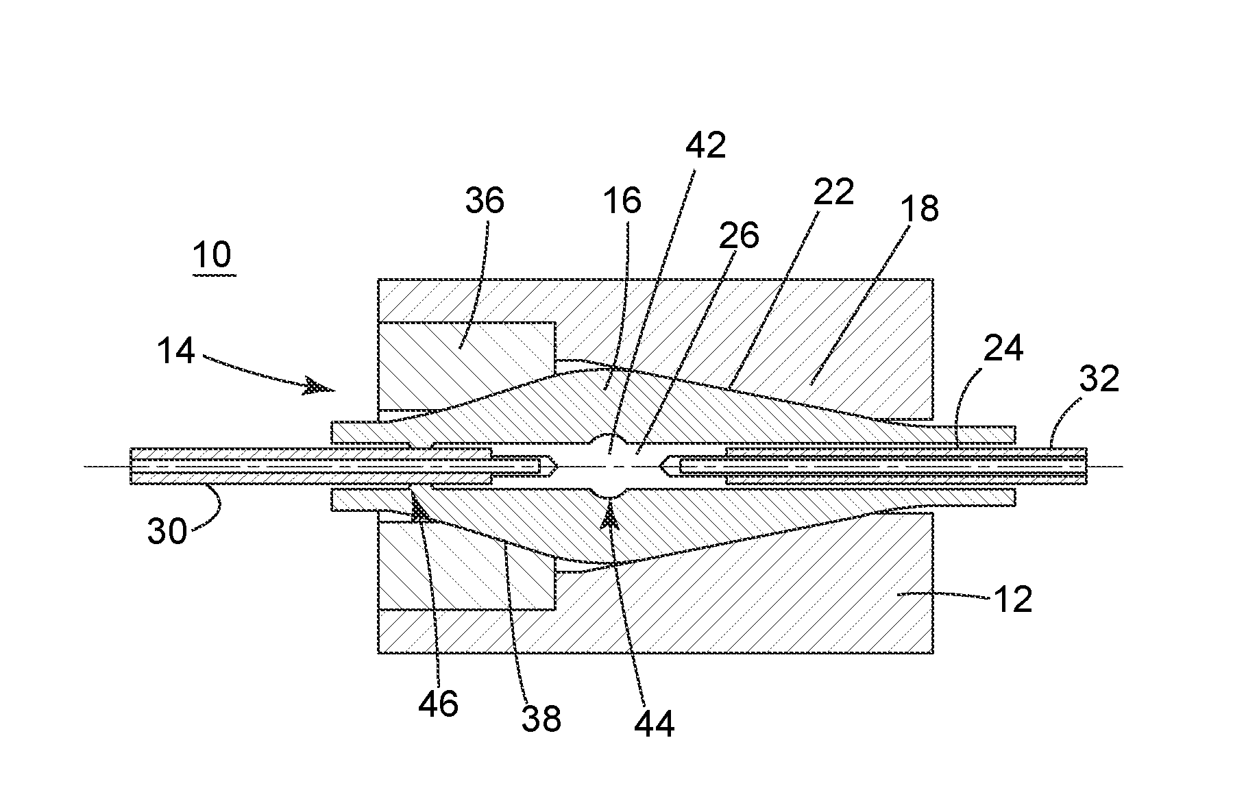
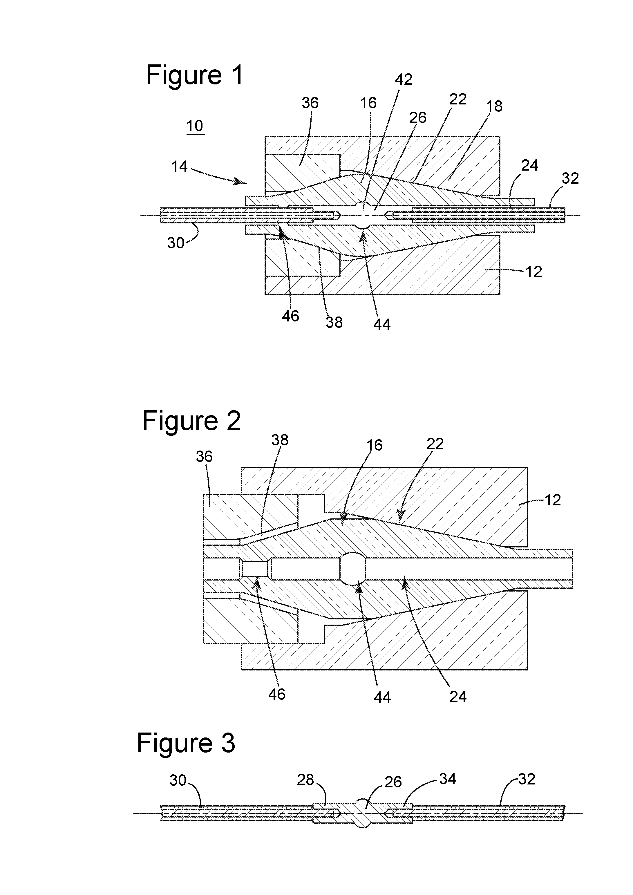
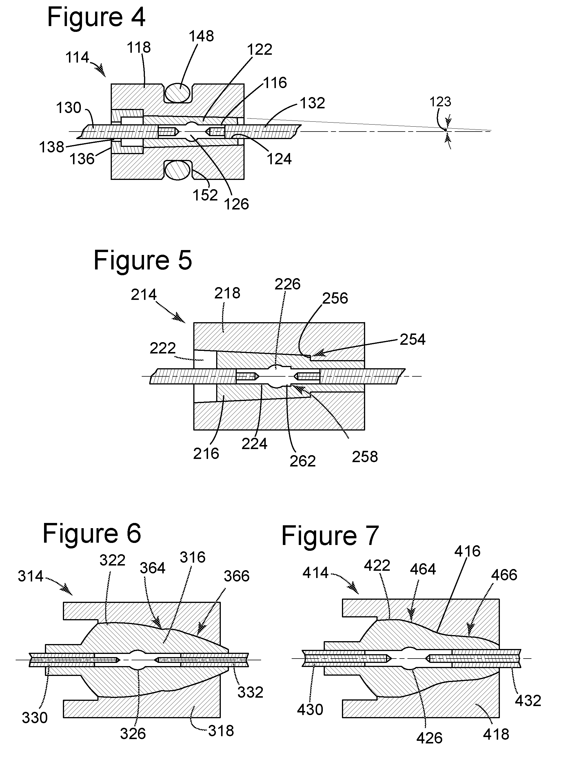
[0031]The following description of the exemplary embodiments refers to the accompanying drawings. The same reference numbers in different drawings identify the same or similar elements. The following detailed description does not limit the invention. Instead, the scope of the invention is defined by the appended claims. The following embodiments are discussed, for simplicity, with regard to the terminology and structure of down hole survey tools or well logging systems. However, the embodiments to be discussed next are not limited to these exemplary systems, but may be applied to other systems.

[0032]Reference throughout the specification to “one embodiment” or “an embodiment” means that a particular feature, structure, or characteristic described in connection with an embodiment is included in at least one embodiment of the subject matter disclosed. Thus, the appearance of the phrases “in one embodiment” or “in an embodiment” in various places throughout the specification is not nec...


PUM


Abstract

A flexible sealing connector for conveying an electrical signal from a first tool portion to a second tool portion, at least one of the first tool portion and the second tool portion having a receiver with a surface defining a receiver passageway, includes a deformable boot in sealing engagement with the surface of the receiver passageway, the deformable boot having a surface defining a boot passageway. The connector further includes an electrical coupler in sealing engagement with the surface of the boot passageway, the coupler having a first end electrically connected to a first electrical line extending from the first tool portion and a second end electrically connected to a second electrical line extending from the second tool portion whereby the first line and the second line are electrically connected, the receiver passageway is sealed by the boot and the boot passageway is sealed by the coupler.

Description

BACKGROUND[0001]1. Technical Field[0002]Embodiments of the subject matter disclosed herein generally relate to sealing electrical connectors, and more particularly, to a sealing electrical connector between a first down hole tool portion and a second down hole tool portion of an oil well survey tool.[0003]2. Discussion of the Background[0004]Down hole survey tool strings are made up of a series of discrete tool portions which are connected together as the survey tool is advanced into the ground. Feed through connectors are employed to facilitate the delivery of an electrical signal from one tool portion to the next without allowing high pressure fluid to enter the string at the connection between adjacent tool portions.[0005]FIG. 11 shows a typical feed through connector 714 seated in a tool portion 720. Feed through connector 714 includes a body 716 having a channel 718 for an O-ring 722. The O-ring 722 seals between the connector body 716 and a seat 728 in the tool portion 720. Co...

Claims


Application Information

Patent Timeline
Patent Type & Authority Applications(United States)
IPC IPC(8): H01R13/52
CPCH01R13/521H01R13/533H02G15/18H01R11/09H02G3/22E21B33/0385
Inventor AYERS, DAVID BLAINE
Owner PRIME DOWNHOLE MANUFACTRUING LLC
Learn More