System and method for determining component temperature requiring maximum cooling

a technology of component temperature and temperature, applied in the field of cooling apparatus, can solve the problems of increasing power consumption, increasing failure rate, creating problems of their own, etc., and achieve the effects of reducing the noise improving the reliability and longevity of the cooling apparatus, and reducing the amount of tim

Active Publication Date: 2006-02-16
GATEWAY
View PDF6 Cites 25 Cited by
  • Summary
  • Abstract
  • Description
  • Claims
  • Application Information

AI Technical Summary

Benefits of technology

[0008] Accordingly, the present invention is directed to determining a temperature for a component that requires a maximum level of the cooling apparatus of the system in which the component is installed. The present invention can permit the cooling apparatus of an information system to operate at less than a maximum level for longer periods of time; and thereby can reduce cooling apparatus noise during operation of the information handling system. Furthermore, the present invention can improve the reliability and longevity of the cooling apparatus of the system by reducing the amount of time during which the cooling apparatus operates at a maximum level.

Problems solved by technology

However, the cooling apparatus, such as fans, can create problems of their own.
These problems include, for example, noise, vibration, increased power consumption, and an increased failure rate due to the fact that these devices have moving parts.
This approach accounts for variations in the manufacturing process of the component, but it does not compensate or take into consideration variations in the ?electronic device into which the electronic component is incorporated, such as an information handling system, and these variations in the system may affect the need for cooling apparatus operation with respect to the electronic component.
Unfortunately, using the current approaches, there is no way to compensate or adjust for the enhanced cooling capacity of systems employing better designed or more capable cooling apparatus.

Method used


Image

  • System and method for determining component temperature requiring maximum cooling
  • System and method for determining component temperature requiring maximum cooling
  • System and method for determining component temperature requiring maximum cooling

Examples


Embodiment Construction

[0015] Reference will now be made in detail to the presently preferred embodiments of the invention, examples of which are illustrated in the accompanying drawings.

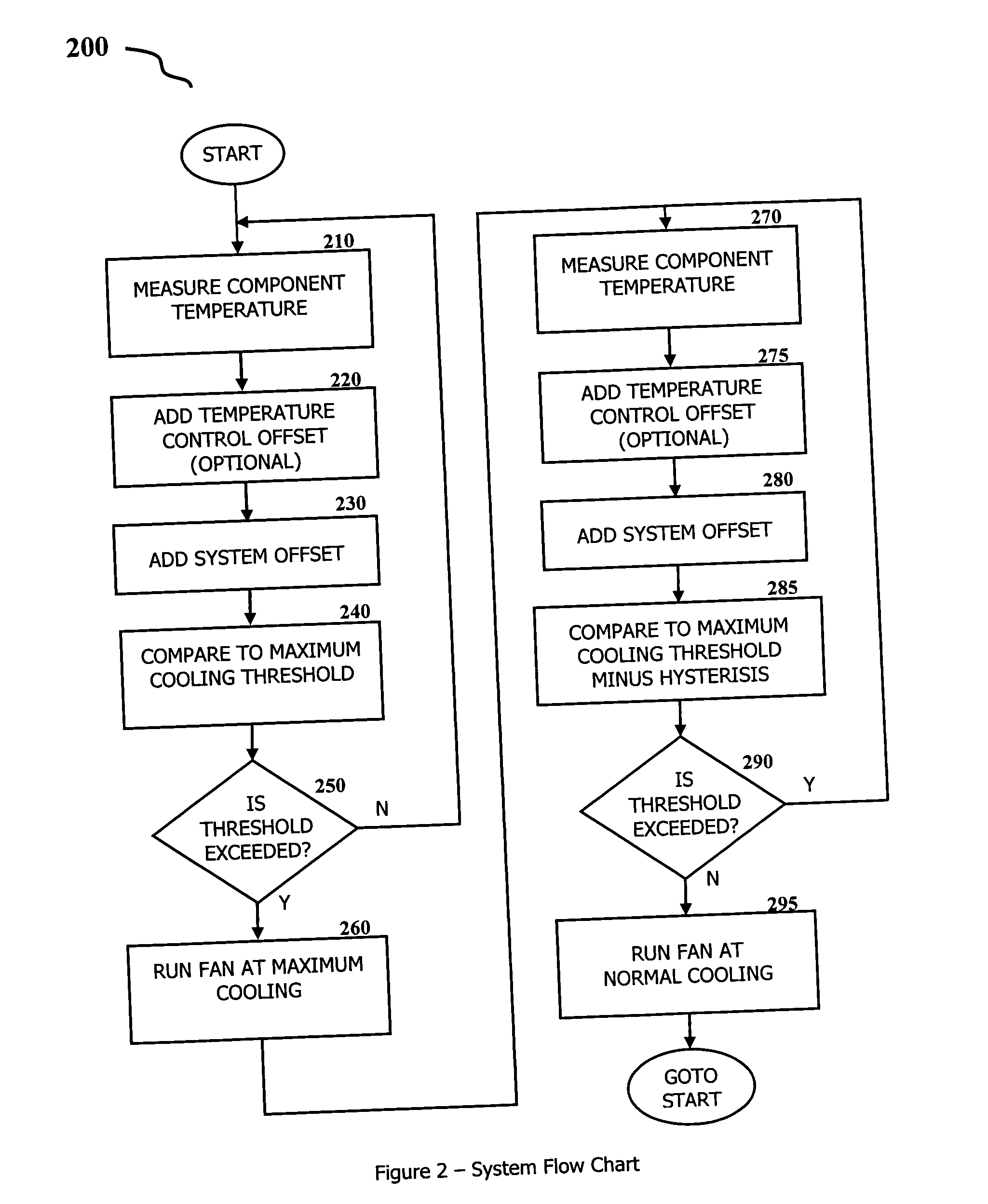
[0016] Referring generally now to FIGS. 1 and 2, exemplary embodiments of the present invention are shown for determining component temperature requiring a maximum level of operation of a cooling apparatus. The cooling apparatus is illustratively employed on an information handling system, although other applications of the invention are possible.

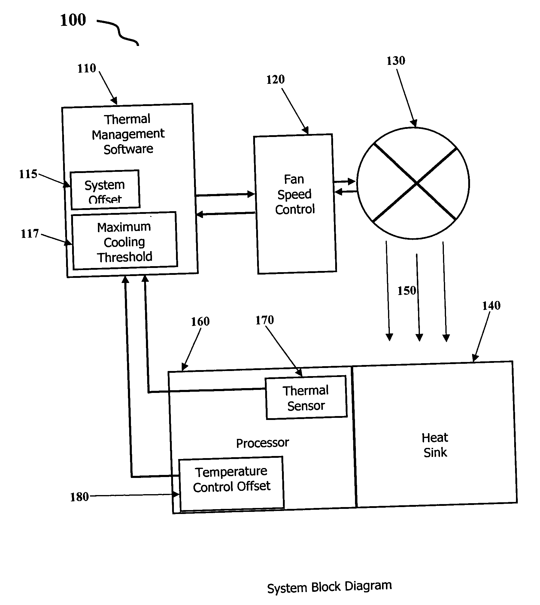
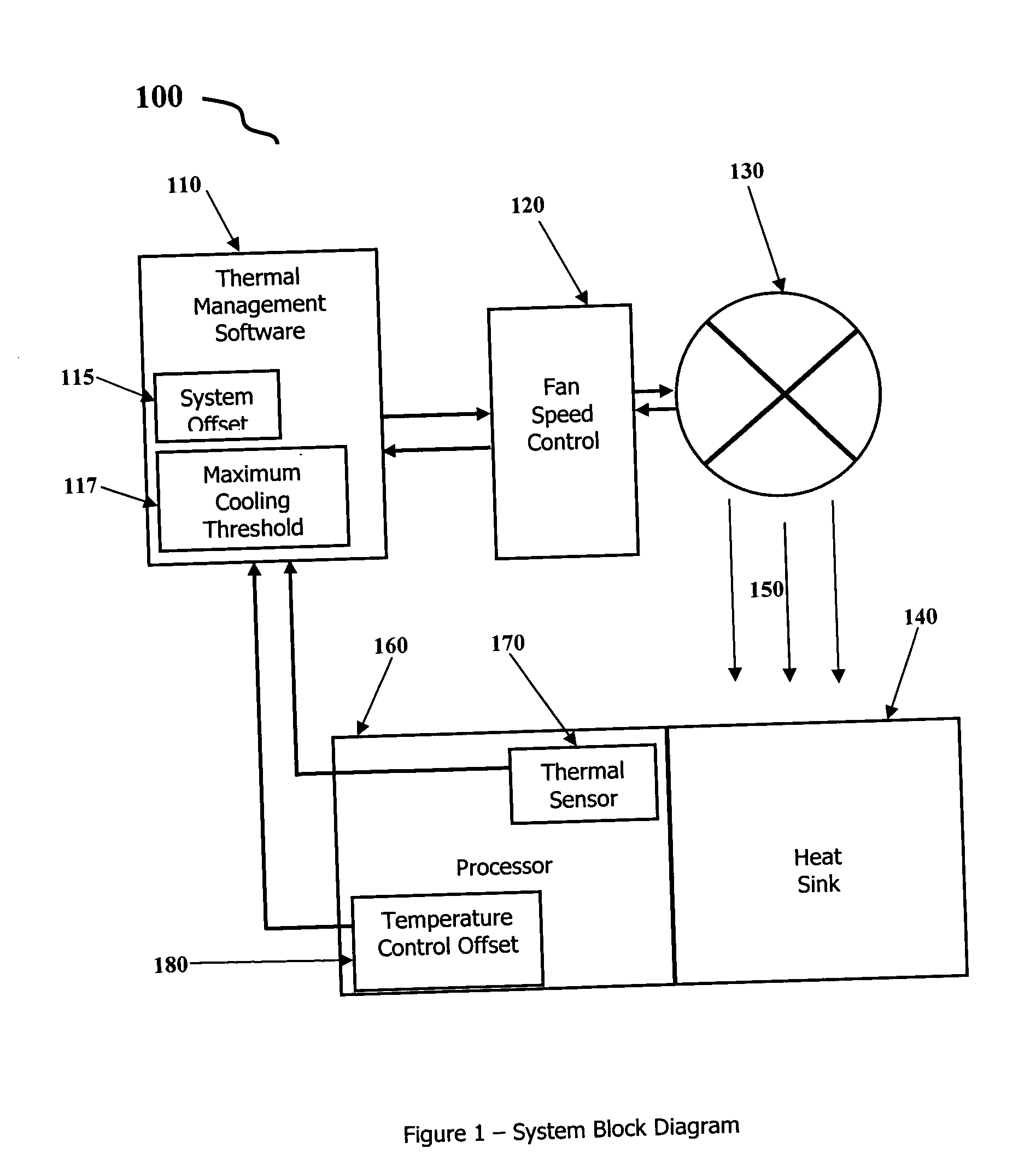
[0017] Referring to FIG. 1, a system block diagram of a system for determining component temperature requiring maximum cooling system operation is shown. In the illustrative system, thermal management software 110 controls the operation of the cooling apparatus. Although the thermal management control may not require run time software control, it may need some initialization on the system. In the illustrative embodiment, the cooling apparatus includes a fan 130 that is controll...


PUM


Abstract

The present invention is directed to a system for determining a temperature of a component that requires a maximum level of cooling apparatus operation. The system monitors the component's temperature, then may add a compensation offset to account for variations in the manufacture of the component, and then adds a compensation offset to account for variation in the system in which the component is installed. The result is used to determine when the system's cooling apparatus needs to be operated at a maximum level of operation. The sum may be compared to a threshold to make this determination. This same mechanism may be used to determine various other cooling system trigger points, both when to increase cooling as well as decrease cooling.

Description

REFERENCE TO RELATED APPLICATIONS [0001] This application claims the priority of U.S. provisional patent application No. 60 / 601,490, filed Aug. 13, 2004, which is incorporated herein in its entirety by reference.FIELD OF THE INVENTION [0002] The present invention generally relates to the field of cooling apparatus for electronic devices, and particularly to a system and method for determining an optimal temperature at which maximum cooling is needed. BACKGROUND OF THE INVENTION [0003] Electronics devices, such as desktop computers, tower computers, servers, tablet computers, notebook computers and other similar devices utilize various methods and apparatus to reduce thermal build-up, or the accumulation of waste heat, within their chassis. These apparatus sometimes include a cooling apparatus, such as a fan, to circulate air within the chassis and / or exchange air inside the chassis with air external to the chassis to help reduce thermal build-up. However, the cooling apparatus, such...

Claims


Application Information

Patent Timeline
Patent Type & Authority Applications(United States)
IPC IPC(8): G05D23/32F25D23/12
CPCG05D23/1905H01L23/34H01L23/467H01L2924/0002H01L2924/00
Inventor FLANIGAN, EDWARD P.THOMAS, KEITH C.
Owner GATEWAY
Why Eureka
Try Eureka