

Drain valve for water closet
A technology for drain valve and toilet, applied in water supply devices, flushing equipment with water tanks, buildings, etc., can solve problems such as easy water leakage, pressing angle, water leakage, sealing failure, etc., to improve reliability and life, simplify conventional structures, reduce The effect of pressing force
- Summary
- Abstract
- Description
- Claims
- Application Information
AI Technical Summary
Problems solved by technology
Method used
Image

Examples
Embodiment Construction
[0023] The technical solutions in the embodiments of the invention will be clearly and completely described below in conjunction with the accompanying drawings in the embodiments of the invention. Obviously, the described embodiments are only some, not all, embodiments of the invention. Based on the embodiments of the present invention, all other embodiments obtained by persons of ordinary skill in the art without making creative efforts fall within the protection scope of the present invention.
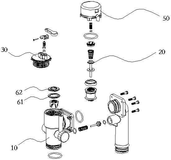
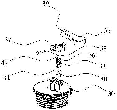
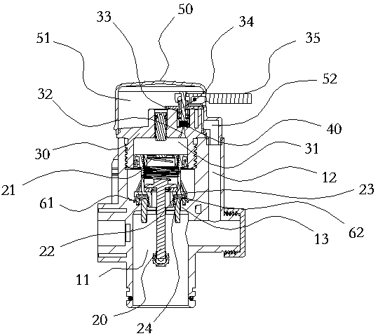
[0024] With reference to the drawings in the specification, a toilet drain valve includes a valve body 10 with a water inlet chamber 11, a valve core assembly 20 is arranged in the water inlet chamber, and an end cover 30 is connected to the valve body above the valve core assembly. , the cavity 31 for back-up pressure is formed between the end cover and the valve core assembly, the valve core assembly is provided with a port 21 communicating with the cavity; the end cover is provided...
PUM
 Abstract
Description
Claims
Application Information