Fixing structure between link and pin in crawler belt, and fixing method thereof

a technology of fixing structure and crawler belt, which is applied in the direction of driving chains, manufacturing tools, hinges, etc., can solve the problems of long processing time and the risk of plastically deformed portion brittle fracture, and achieve excellent strength, reduce material cost, and increase contact area

Inactive Publication Date: 2005-05-03
KOMATSU LTD
View PDF8 Cites 14 Cited by
  • Summary
  • Abstract
  • Description
  • Claims
  • Application Information

AI Technical Summary

Benefits of technology

[0011]The present invention aims to improve a fixing structure and a fixing method that are described in the prior art publications as mentioned above. Accordingly, the present invention has an object to provide a fixing structure between a link and a pin in a crawler belt which can reduce pressing force for the purpose of plastic deformation as well as achieve firm fixing between the link and the pin in the crawler belt.

Problems solved by technology

Further, since plastic deformation is applied to the portion in which the surface hardness is high, there was a risk that a brittle fracture is generated in the plastically deformed portion, for example, by applying a strong pressing force at a stroke so as to perform plastic deformation.
On the contrary, there was a problem that a long time is required for processing, in the case that pressing force is applied little by little while preventing brittle fracture from being generated.

Method used


Image

  • Fixing structure between link and pin in crawler belt, and fixing method thereof
  • Fixing structure between link and pin in crawler belt, and fixing method thereof
  • Fixing structure between link and pin in crawler belt, and fixing method thereof

Examples


Embodiment Construction

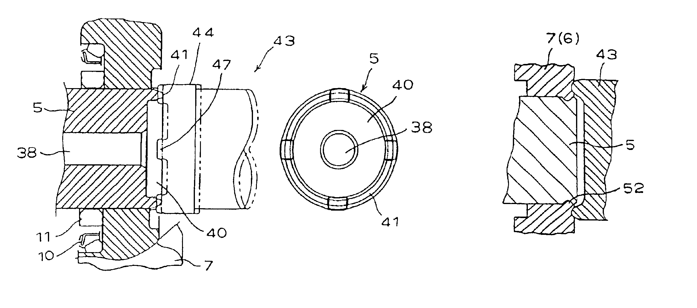
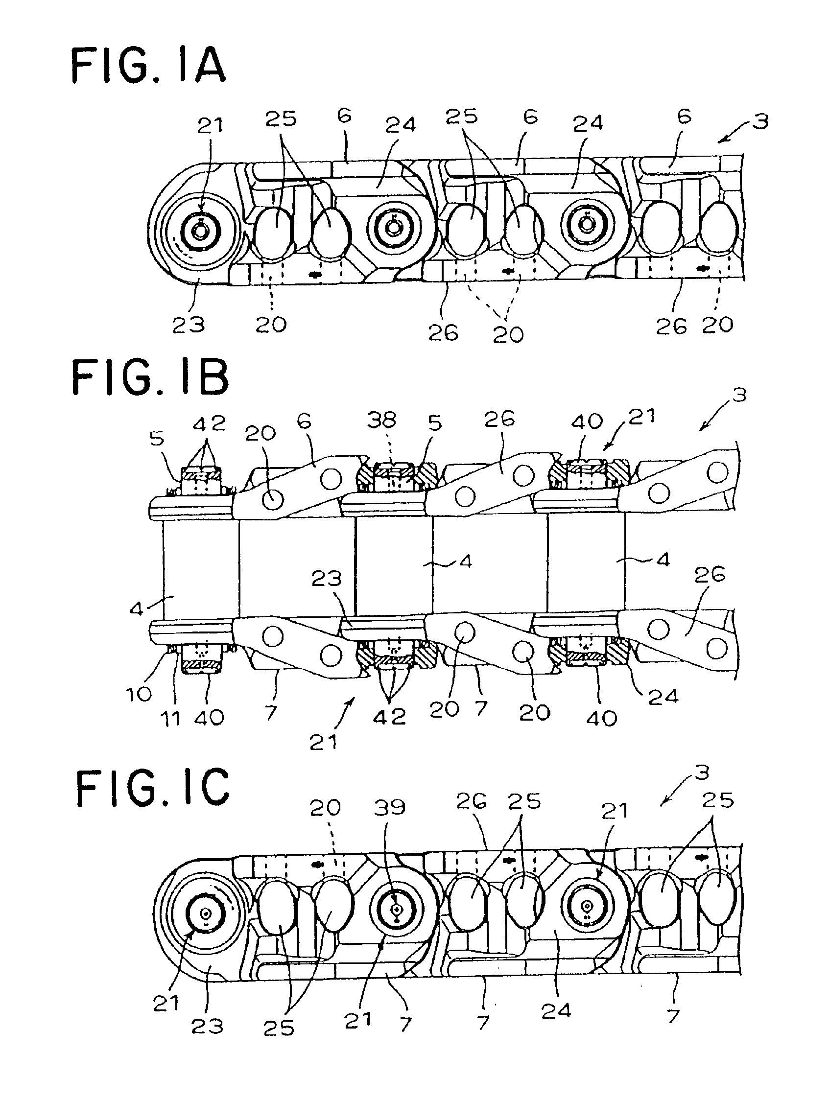
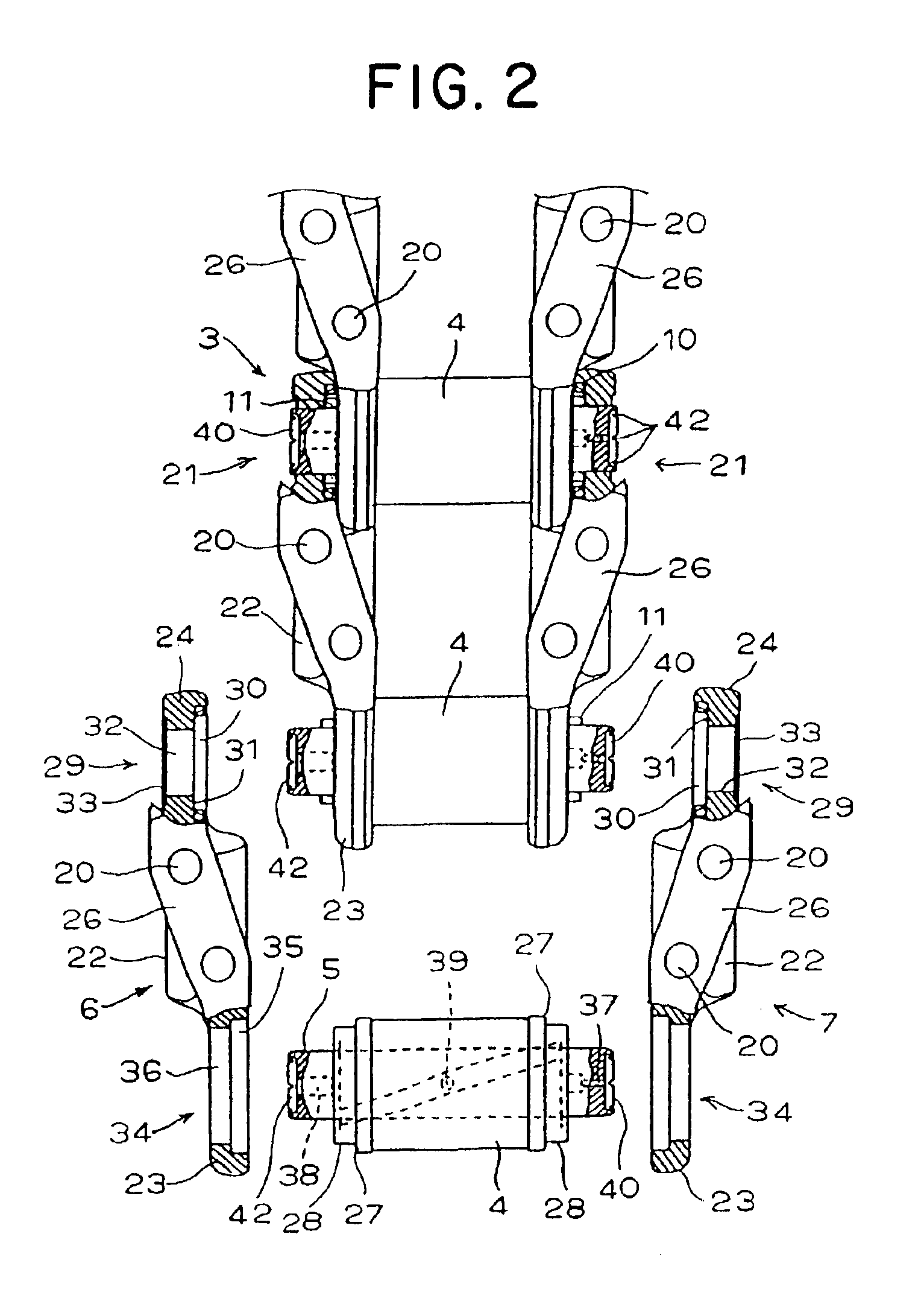
[0046]Description will be particularly given below of preferred embodiments according to the present invention with reference to the accompanying drawings. FIGS. 1A to 1C are schematic views of a structure each showing a part of a link chain in a crawler belt according to the present invention, and FIG. 2 is an exploded view showing a part of the link chain in an exploded manner.

[0047]In FIGS. 1 and 2, the crawler belt 1 as shown in FIG. 15 is constituted by a link chain 3 and a plurality of track blocks 2. The link chain 3 is composed of a pair of left and right plural endless links 6 and 7 connected to each other so as to form joints. The plurality of track blocks 2 as shown in FIG. 15 for contacting the ground surface are bolted to track-block-mounting holes 20 in the links 6 and 7. The crawler belt 1 is rotatably wound around travelling drive wheels which includes drive sprockets arranged in a rear portion of a track-type vehicle such as a work machine or the like (not shown), i...


PUM

PropertyMeasurementUnit
angleaaaaaaaaaa
surface hardnessaaaaaaaaaa
hardnessaaaaaaaaaa

Abstract

In a crawler belt comprising pairs of opposite links connected endlessly via pins press-fitted into the links, fixing surfaces of pins or links are successively pressed and deformed from the fixing surfaces in an axial direction along the circumferences inside or outside of openings of pin-press-fitting holes by means of local pressing in the axial direction, whereby the end portions of the pins or part of the circumferences of the openings in the links are expanded or narrowed in diameter. The expanded or narrowed portions are fixedly engaged with the opposing engaging spaces. The surface hardness of the expanded or narrowed portions is set to be lower than that of the other portions. With such structure and method, the links and pins can be easily and firmly connected with sufficient holding force in the axial direction, securing accurate, quick and easy fixing of pins and assembling of pins and links.

Description

BACKGROUND OF THE INVENTION[0001]1. Field of the Invention[0002]The present invention relates to fixing structure and fixing method between a link and a pin in a crawler belt which is used in a track-type vehicle.[0003]2. Description of the Related Art[0004]Conventionally, as shown in FIG. 15, in a crawler belt 1 which is used for a track-type vehicle in a work machine such as a bulldozer or a tractor, a plurality of track blocks 2 to contact the ground surface are mounted to an endless link chain 3 by means of bolt fastening. Then, as shown in FIG. 2 in which a part of the link chain is being exploded, when the crawler belt is being assembled, a bushing 4 is interposed between connecting portions of opposing links 6 and 7 and end portions of the bushing 4 are inserted into bushing insertion holes 34. In this state, a pin 5 is being inserted into the bushing 4. Further, end portions of the pin 5 protruding from the bushing 4 are inserted into pin insertion holes 32 and 33 of another...

Claims


Application Information

Patent Timeline
Patent Type & Authority Patents(United States)
IPC IPC(8): B62D55/20B62D55/21
CPCB62D55/21Y10T29/49934Y10S59/901
Inventor YAMAMOTO, TEIJI
Owner KOMATSU LTD
Why Eureka
Try Eureka