Combined type equipment for manufacturing spherical powder through rotating electrode

A technology of rotating electrode and spherical powder, applied in the field of powder metallurgy, can solve the problems of high equipment failure rate, serious vibration, low rotation speed, etc., and achieve the effect of improving the rate of fine powder, reliability and life.

Active Publication Date: 2017-11-24
BAOJI FANMEI MATERIAL TECH
View PDF2 Cites 0 Cited by
  • Summary
  • Abstract
  • Description
  • Claims
  • Application Information

AI Technical Summary

Problems solved by technology

[0004] The rotating electrode method has a history of about 50 years, but there are several major disadvantages: 1. The speed is low, generally not exceeding 12000 rpm
2. The vibration is serious, and the bearing is easily damaged
3. Use carbon brushes to conduct electricity, the carbon brushes are in contact with the collector, and the frict

Method used


Image

  • Combined type equipment for manufacturing spherical powder through rotating electrode
  • Combined type equipment for manufacturing spherical powder through rotating electrode
  • Combined type equipment for manufacturing spherical powder through rotating electrode

Examples


Embodiment Construction

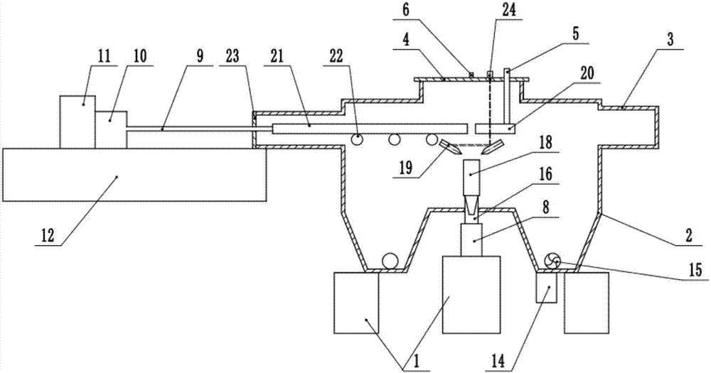
[0022] combined with figure 1 , 2 , 3 describe an embodiment of the present invention.

[0023] An equipment for manufacturing spherical powder with a composite rotating electrode, including a furnace body 2, and the furnace body 2 is located on a base 1; the right end of the furnace body 2 has a vacuum connecting pipe 3 connected to a vacuum system, and the left end is provided with a bed base 12 , the guide rail on the upper end surface of the bed base 12 is horizontally provided with a first electric spindle 11 and a current collecting device 10, the first electric spindle 11 is coaxially connected with a current collecting device 10, and the current collecting device 10 is on the same The shaft is connected with a transmission shaft 9, and the transmission shaft 9 extends into the left part of the furnace body 2 in a sealed manner and conducts flow through the current collector 10. The rod-shaped blank 21 is supported in the left part of the furnace body 2 by a horizontal...


PUM


Abstract

The invention discloses combined type equipment for manufacturing spherical powder through a rotating electrode. The right end of a furnace body located on a base is provided with a vacuum connection pipe, and the vacuum connection pipe is connected with a vacuum system. A bed stand arranged at the left end of the furnace body is horizontally provided with a first electric main shaft and a current collecting device, wherein the first electric main shaft and the current collecting device are linked coaxially. A transmission shaft is coaxially linked to the current collecting device. The transmission shaft extends into the left portion of the furnace body in a sealed manner, and current guiding is conducted through the current collecting device. A rodlike blank is supported on the left portion inside the furnace body, and the tail end of the rodlike blank is linked with the front end of the transmission shaft. A transferred arc plasma gun is horizontally arranged on the right portion inside the furnace body. A second electric main shaft is vertically mounted on a vertical lifting mechanism at the upper end of the base and extends into the lower portion of the furnace body in a sealed manner, and the upper end of the second electric main shaft is coaxially linked with the rotating electrode. The rotating electrode is located under the front end of the rodlike blank. Two non-transferred-arc plasma guns are symmetrically arranged at the two sides of the rotating electrode in an inclined manner. By means of the combined type equipment, the rotating electrode is separated from electric conduction, and fusion is separated from tossing-out; and the fine powder rate is increased, and production efficiency is improved.

Description

technical field [0001] The invention belongs to the technical field of powder metallurgy, and in particular relates to a device for manufacturing spherical powder with a composite rotating electrode. Background technique [0002] There are three main methods of producing metal spherical powder: blowing method; rotating disk method; rotating electrode method. For the latter two, it has been proved theoretically that the relationship between the diameter of the powder and the rotational speed and the diameter of the electrode: If the particle size of the powder is small, it is necessary to increase the speed or increase the diameter of the electrode [0003] The blowing method is to use high-pressure argon to blow the molten metal into droplets, and the droplets are cooled into spherical shapes while flying in the air. This method can produce very fine powder, but the shape of the ball is not good, and there are cavitation phenomena. The rotating disk method has a wide ran...

Claims


Application Information

Patent Timeline
IPC IPC(8): B22F9/14B22F1/00
CPCB22F9/14B22F1/065Y02P10/25
Inventor 胡宗式佟大新
Owner BAOJI FANMEI MATERIAL TECH
Why Eureka
Try Eureka