

Permanent magnet fixing structure, fixing method, permanent magnet motor and vehicle
A fixed structure, permanent magnet motor technology, applied in the direction of magnetic circuit shape/style/structure, manufacturing motor generators, electromechanical devices, etc., can solve the problems of permanent magnet fragmentation, permanent magnet surface damage, low efficiency, etc., to achieve increased Great reliability and lifespan, reduce manufacturing risk, and speed up production efficiency
- Summary
- Abstract
- Description
- Claims
- Application Information
AI Technical Summary
Problems solved by technology
Method used
Image

Examples
Embodiment 1
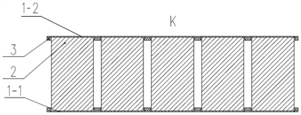
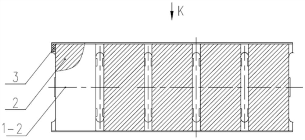
[0036] Such as figure 1 and figure 2 As shown, this embodiment provides a permanent magnet fixing structure, which includes a first cover plate 1-1 and a second cover plate 1-2, and the first cover plate 1-1 and the second cover plate 1-2 It is used to respectively fix the two ends of several permanent magnets 2 to realize the self-locking of the axial direction of the permanent magnets 2; the permanent magnets 2 are arranged in sequence according to the polarity direction of the permanent magnets.
[0037] exist figure 1 Among them, the permanent magnet 2 is placed between the first cover plate 1-1 and the second cover plate 1-2, and is not hit by the external through-slot rod during the production process, which can well protect the surface of the permanent magnet. At the same time, the phenomenon of permanent magnet fragmentation will not occur. During use, it is not affected by external vibration, impact and other factors, so that the permanent magnet is well adapted t...
Embodiment 2
[0053] In this embodiment, there is also provided a permanent magnet fixing method using the permanent magnet fixing structure as described above, which includes:
[0054] Preset the polarity direction of the permanent magnet;
[0055] The permanent magnets are sequentially arranged according to the preset polarity direction of the permanent magnets, and the two ends are respectively fixed between the first cover plate and the second cover plate, so as to realize the self-locking of the permanent magnets in the axial direction;
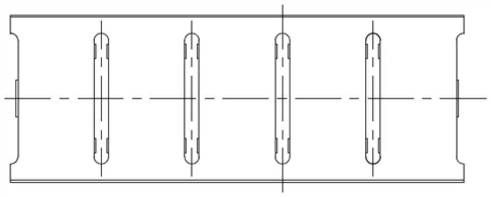
[0056] Insert the fixed permanent magnet directly into the permanent magnet slot in the stamping sheet.
Embodiment 3
[0058] In this embodiment, there is also provided a permanent magnet motor, which particularly includes an iron core and a permanent magnet, and the permanent magnet is fixed by the above-mentioned permanent magnet fixing structure.
PUM
 Abstract
Description
Claims
Application Information