
Weatherproof electrical enclosure

a technology for electrical enclosures and enclosures, applied in the direction of electrical apparatus, casings/cabinets/drawers, casings/cabinets/drawers details, etc., can solve the problems of insufficient protection of wiring devices, injury of workers servicing downstream electrical equipment, etc., and achieve the effect of removing the knock-out plug

Inactive Publication Date: 2006-02-23
LEVITON MFG
View PDF19 Cites 27 Cited by
  • Summary
  • Abstract
  • Description
  • Claims
  • Application Information

AI Technical Summary

Benefits of technology

[0009] The present invention obviates the disadvantages and limitations of prior art weatherproof junction boxes while providing security against unauthorized access and tampering of the wiring device in the weatherproof junction box. The weatherproof box for the wiring device includes a recessed port capped with a non-reusable knock-out plug located at an end of the port. The port can be threaded or unthreaded, and the knock-out plug can be removed. The port may be used to receive an electrical conduit or cable having electrical conductors to enter the weatherproof box.

Problems solved by technology

But, when the cover is open, inadequate protection is often provided to the wiring device, particularly when an electrical plug is connected to a receptacle.
Unauthorized access and / or tampering with the electrical wiring devices of the junction box can result in injury to workers servicing downstream electrical equipment.

Method used


Image

  • Weatherproof electrical enclosure
  • Weatherproof electrical enclosure
  • Weatherproof electrical enclosure

Examples


Embodiment Construction

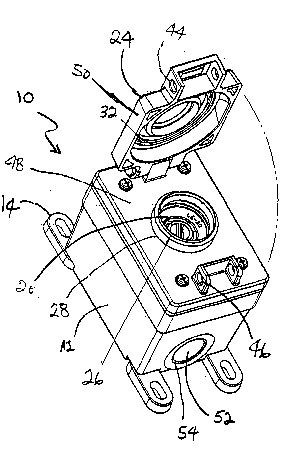
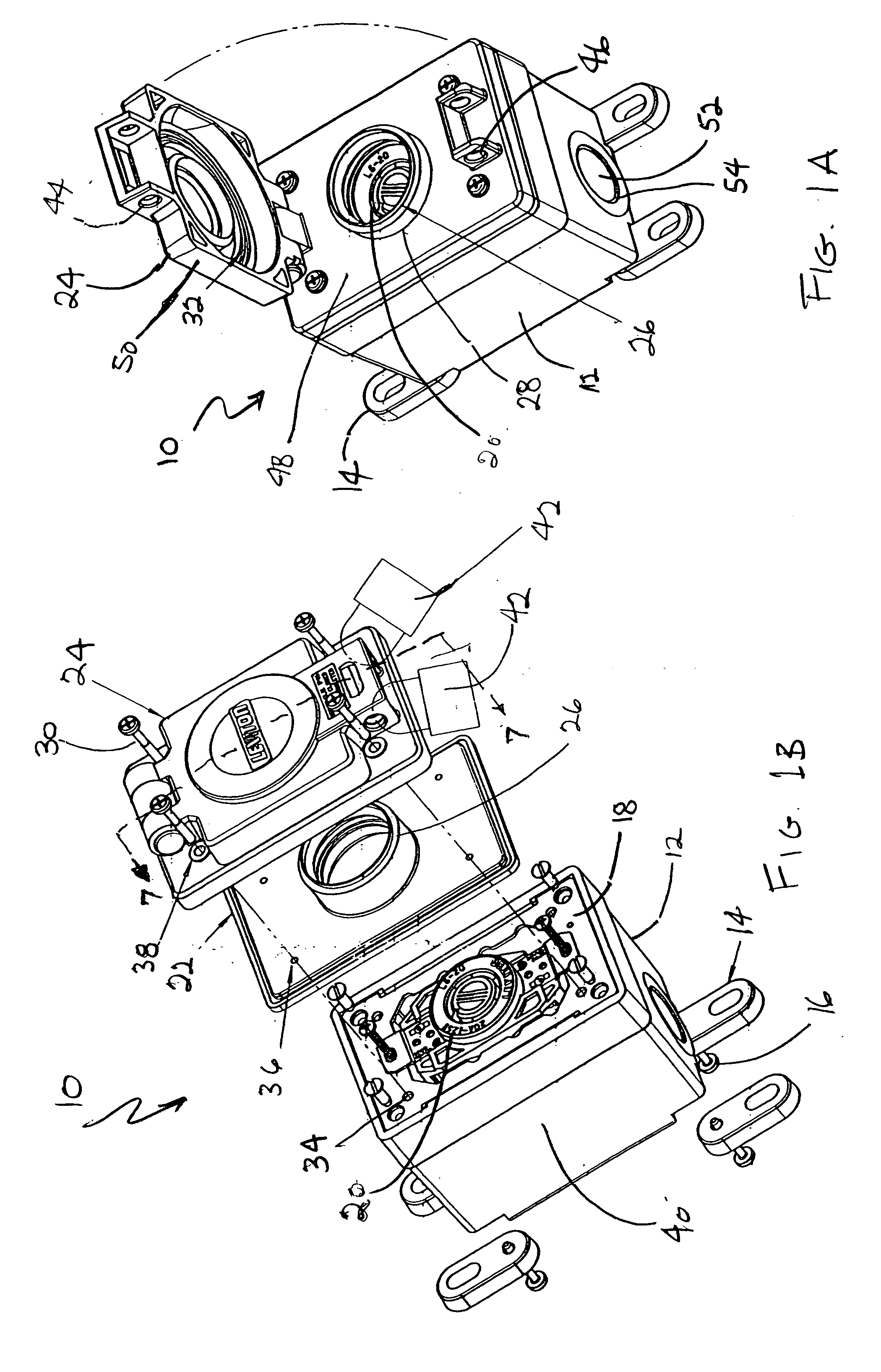
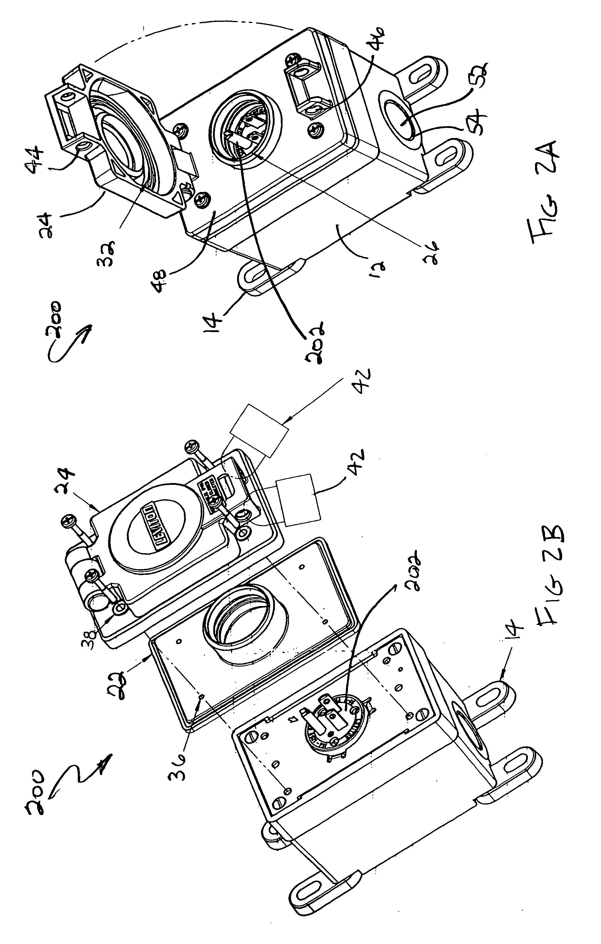
[0030]FIG. 1A illustrates an implementation of the weatherproof junction box 10. FIG. 1B illustrates an exploded assembly view of the weatherproof junction box 10 of FIG. 1A. The weatherproof box 10 includes a box 12 having mounting holes (not shown) for mounting the weatherproof box to a mounting surface such as a wall. The weatherproof junction box has mounting lugs 14 that can swivel ninety degrees to provide a wide variety of surface mounting capabilities. The mounting lugs 14 are connected to the box 10 with screws 16 threaded into blind threaded openings (not shown) in the base of the box 10. If desired, the mounting lugs can be removed and the box can be mounted from behind using the blind threaded openings which were used for the mounting lugs. A metal adapter plate 18 can be attached to the box 10. The adapter plate 18 can include holes at appropriate locations to adapt the box 10 to receive a variety of wiring devices.

[0031] The box 12 includes a removable knock-out 52. T...


PUM


Abstract

A weatherproof junction box can also provide security against unauthorized access and tampering of a wiring device in the weatherproof junction box. The weatherproof box for the wiring device includes a recessed port capped with a knock-out plug located at an end of the recessed port. When the knock-out plug is removed, the recessed port may be used to receive an electrical conduit or cable having electrical conductors to enter the weatherproof box.

Description

[0001] This application claims the benefit of the filing date of a provisional application having Ser. No. 60 / 591,896, which was filed on Jul. 28, 2004.BACKGROUND OF THE INVENTION [0002] 1. Field of the Invention [0003] The present invention relates generally to housings, enclosures, covers for electrical fixtures such as electrical outlets, switches, and plugs. More particularly, the invention is directed toward a new improved weatherproof enclosure for a wiring device [0004] 2. Description of Related Art [0005] Outdoor weatherproof boxes for electrical wiring devices such as receptacles, switches etc., are known in the industry. Such boxes typically have a self-closing cover which forms a weather tight fit with the box and weather tight openings for receiving electrical conductors. [0006] The primary purpose of the cover, when closed, is to prevent water, dust etc. from entering the box and the electrical wiring device. Prior art covers of weatherproof boxes provide some protectio...

Claims


Application Information

Patent Timeline
Patent Type & Authority Applications(United States)
IPC IPC(8): H02G3/14
CPCH02G3/14H02G3/088
Inventor CASTALDO, COSMOROCCARO, PATRICIA
Owner LEVITON MFG
Learn More