
Thrust reverser system electro-mechanical brake manual release mechanism

a thrust reverser and electro-mechanical technology, applied in the direction of machines/engines, vessels, transportation and packaging, etc., can solve the problems of insufficient speed and runway distance of landing gear brakes of aircraft, inability to slow down aircraft in the required amount of runway distance, maintenance and repair processes of thrust reverser systems,

Inactive Publication Date: 2006-03-02
HONEYWELL INT INC
View PDF16 Cites 27 Cited by
  • Summary
  • Abstract
  • Description
  • Claims
  • Application Information

AI Technical Summary

Benefits of technology

[0012] The present invention provides a manual release mechanism for a thrust reverser actuation system electromechanical brake. In one embodiment, and by way of example only, a system for moving an aircraft thrust reverser includes a power drive unit, a thrust reverser actuator assembly, an electromechanical brake, and a manual brake release mechanism. The power drive unit is operable to rotate and thereby supply a rotational drive force. The thrust reverser actuator assembly is coupled to receive the rotational drive force and is operable, in response thereto, to selectively move the thrust reverser between a stowed position and a deployed position. The electromechanical brake is coupled to the power drive unit, is configured to receive a brake release command, and is operable, in response thereto, to selectively move between an engage and a disengage position, to thereby prevent and allow, r

Problems solved by technology

When a jet-powered aircraft lands, the landing gear brakes and aerodynamic drag (e.g., flaps, spoilers, etc.) of the aircraft may not, in certain situations, be sufficient to slow the aircraft down in the required amount of runway distance.
Nonetheless, thrust reverser systems may be subject to maintenance and repair processes.
During such processes, power to the locks may not be available, thereby locking the actuators, PDU, and / or thrust reversers against movement.

Method used


Image

  • Thrust reverser system electro-mechanical brake manual release mechanism
  • Thrust reverser system electro-mechanical brake manual release mechanism
  • Thrust reverser system electro-mechanical brake manual release mechanism

Examples


Embodiment Construction

[0022] Before proceeding with the detailed description, it is to be appreciated that the described embodiment is not limited to use in conjunction with a specific thrust reverser system design. Thus, although the description is explicitly directed toward an embodiment that is implemented in a cascade-type thrust reverser system, in which transcowls are used as the moveable thrust reverser component, it should be appreciated that it can be implemented in other thrust reverser actuation system designs, including those described above and those known now or hereafter in the art.

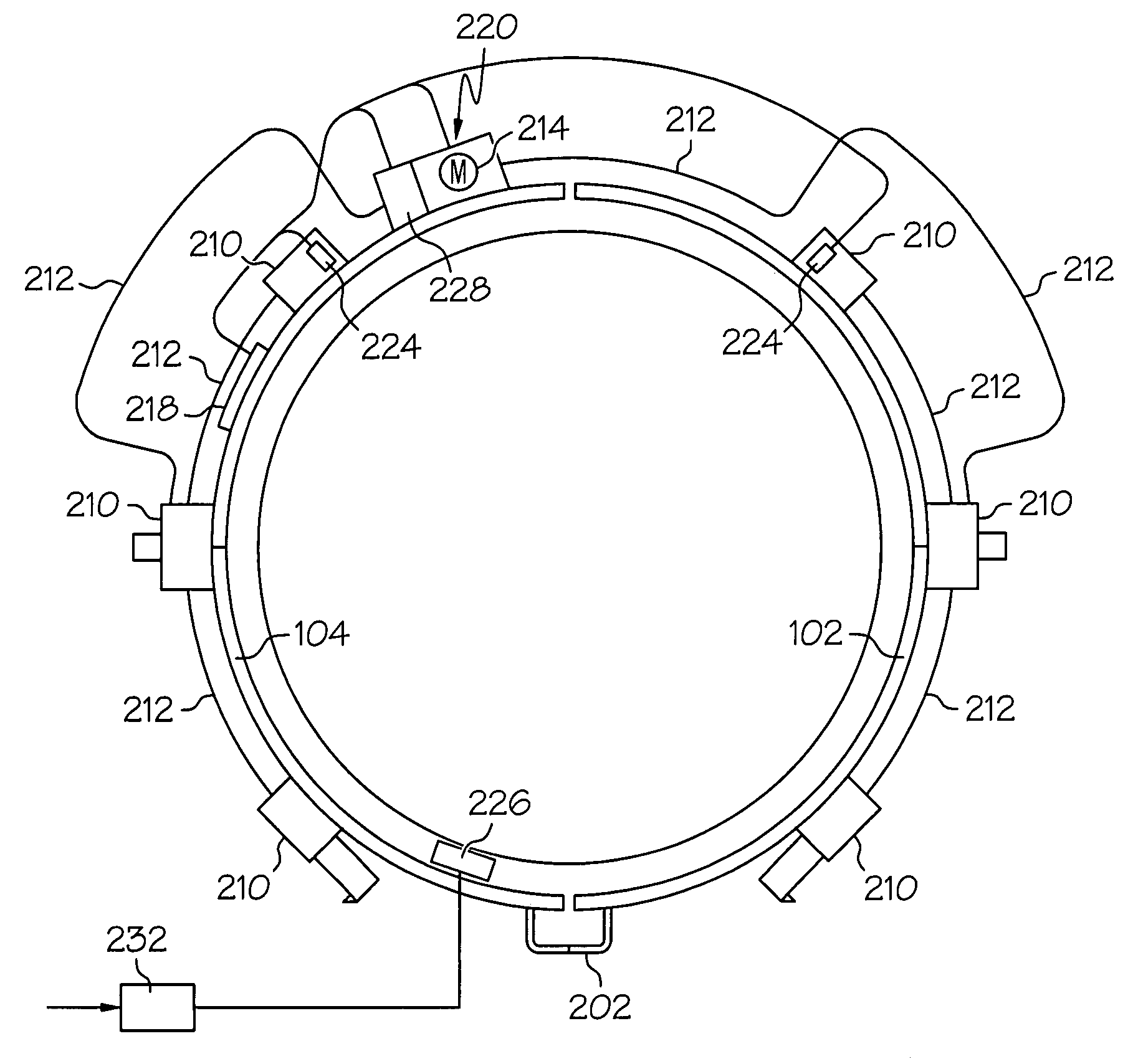
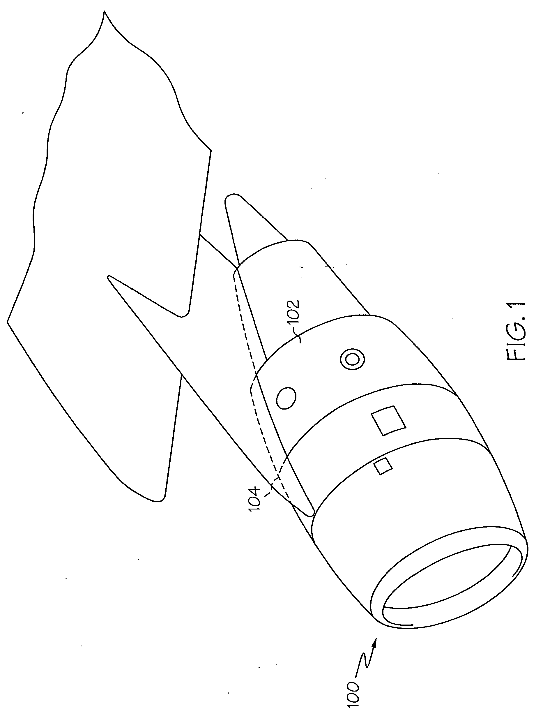
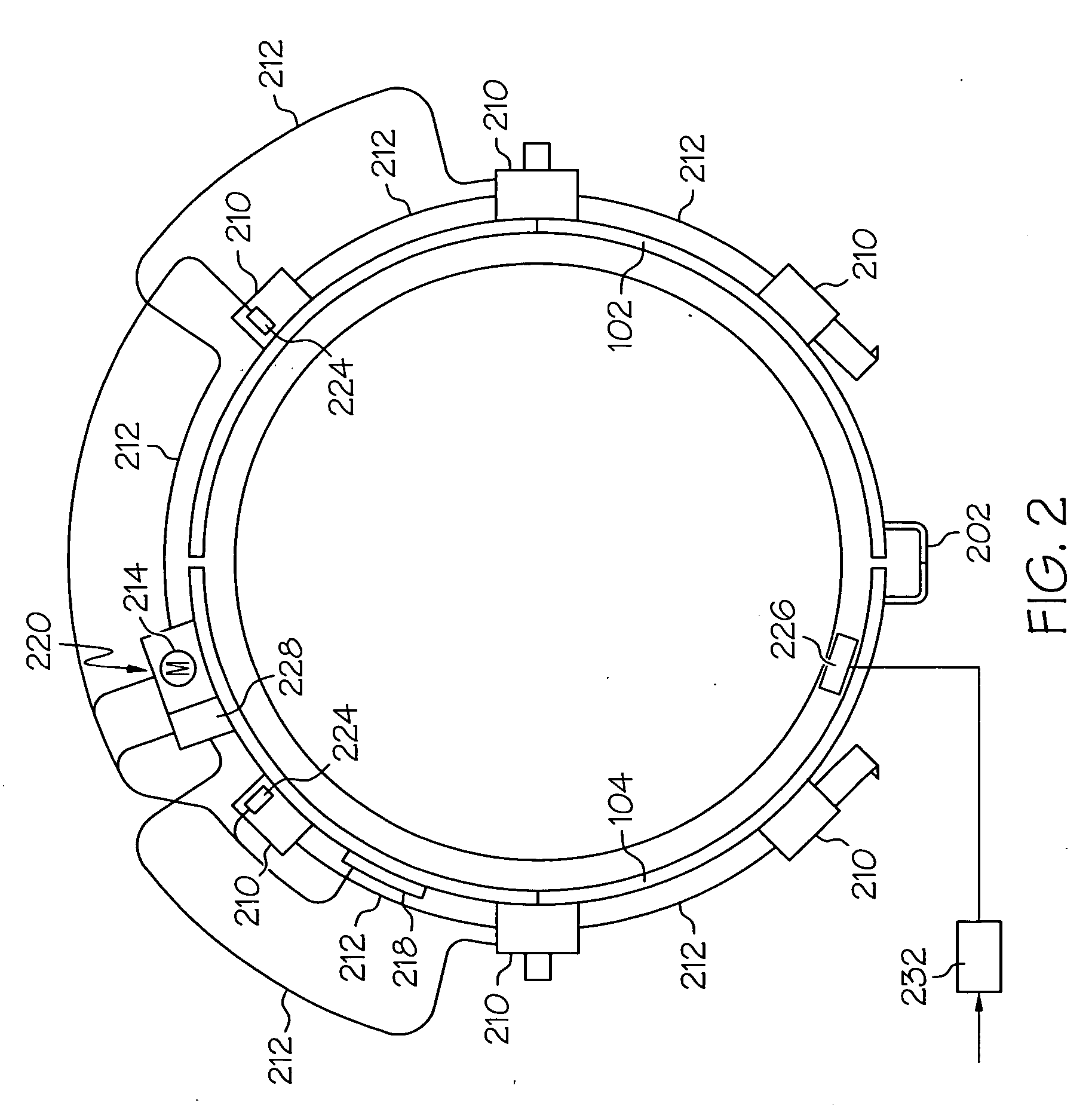
[0023] Turning now to the description, and with reference first to FIG. 1, a perspective view of portions of an aircraft jet engine fan case 100 that incorporates a cascade-type thrust reverser is depicted. The engine fan case 100 includes a pair of semi-circular transcowls 102 and 104 that are positioned circumferentially on the outside of the fan case 100. The transcowls 102 and 104 cover a plurality of non-i...


PUM


Abstract

A manual release mechanism for a thrust reverser actuation system electromechanical brake includes a first release plate, a second release plate, at least two balls, and a handle. The first and second release plates each have grooves formed therein that have a cam surface located at a predetermined angle. The release plates face one another such that the grooves in each plate are substantially aligned, and the balls are each positioned in the aligned grooves. The first release plate is configured to rotate, and the second release plate is configured to translate. The handle is coupled to the first release plate to allow manual rotation thereof. In response to rotation of the first release plate, the second release plate will translate and disengage the electromechanical brake.

Description

TECHNICAL FIELD [0001] The present invention relates to aircraft engine thrust reverser actuation systems and, more particularly, to a manual release mechanism for a thrust reverser actuation system electromechanical brake. BACKGROUND [0002] When a jet-powered aircraft lands, the landing gear brakes and aerodynamic drag (e.g., flaps, spoilers, etc.) of the aircraft may not, in certain situations, be sufficient to slow the aircraft down in the required amount of runway distance. Thus, jet engines on most aircraft include thrust reversers to enhance the braking of the aircraft. When deployed, a thrust reverser redirects the rearward thrust of the jet engine to a generally or partially forward direction to decelerate the aircraft. Because at least some of the jet thrust is directed forward, the jet thrust also slows down the aircraft upon landing. [0003] Various thrust reverser designs are commonly known, and the particular design utilized depends, at least in part, on the engine manuf...

Claims


Application Information

Patent Timeline
IPC IPC(8): F02K1/54
CPCF02K1/766F16D2127/04F16D2125/38F16D2121/22
Inventor HANLON, CASEYCHRISTENSEN, DONALD J.CHAKKERA, KEVIN K.
Owner HONEYWELL INT INC
Learn More