
Light communication system and illumination apparatus therefor

a technology of communication system and illumination apparatus, applied in the field of light communication system, can solve the problems of inability to achieve high-reliability communication, and inability to communicate with visible light, and achieve high-reliability, high-performance light wireless communication

Inactive Publication Date: 2006-03-02
AVAGO TECH ECBU IP (SINGAPORE) PTE LTD
View PDF4 Cites 15 Cited by
  • Summary
  • Abstract
  • Description
  • Claims
  • Application Information

AI Technical Summary

Benefits of technology

"The present invention is a light communication system that allows for two-way communication between an illumination apparatus and a terminal. This is achieved by setting a reserved time during which the illumination apparatus is turned off to facilitate light communication. The lighting apparatus can be set up to communicate with multiple terminals and can use visible or infrared light for communication. The length of the reserved time is synchronized with the voltage waveform of the commercial power source. The system can also allow for intercommunication between communication terminals and can include multiple illumination apparatuses set at a common reserved time. The light-emitting elements used for illumination and communication can be adjusted to different emission spectra and can include multiple light-emitting elements for different wavelengths. The system provides higher performance light wireless communication than previous methods."

Problems solved by technology

(See, for example, JP (Kokai) [Unexamined Japanese Patent Publication] 1-264,420; JP (Kokai) [Unexamined Japanese Patent Publication] 1-292,918; JP (Kokai) [Unexamined Japanese Patent Publication] 11-163,795) However, in the case of communications using visible light, even in places with relatively low illumination intensity, interference between the illumination light and communication light occurs, and high-reliability communication is not possible.
For instance, communication using infrared light is possible in a location where the illumination intensity has temporarily decreased, but this is not possible in the case of visible light communications.
This problem becomes particularly important when two-way communication is necessary.
Problems will rarely occur when lighting equipment is used for light communications and modulated light waves are emitted from lighting equipment in one direction (transmission of regional data or release of data specifying a location, or another application) as long as the lighting equipment continuously emits light.
However, light power generated by the lighting equipment interferes with communications when there is a communication device at the same place and communication occurs between this device and the lighting equipment or the other communication device.

Method used


Image

  • Light communication system and illumination apparatus therefor
  • Light communication system and illumination apparatus therefor
  • Light communication system and illumination apparatus therefor

Examples


Embodiment Construction

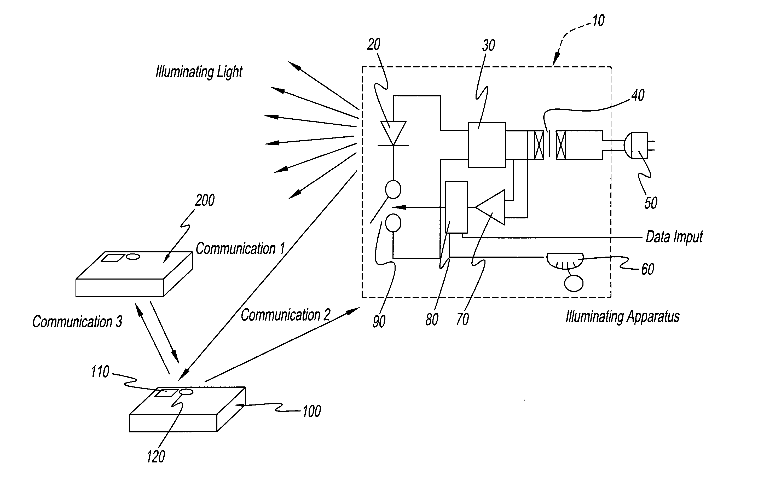
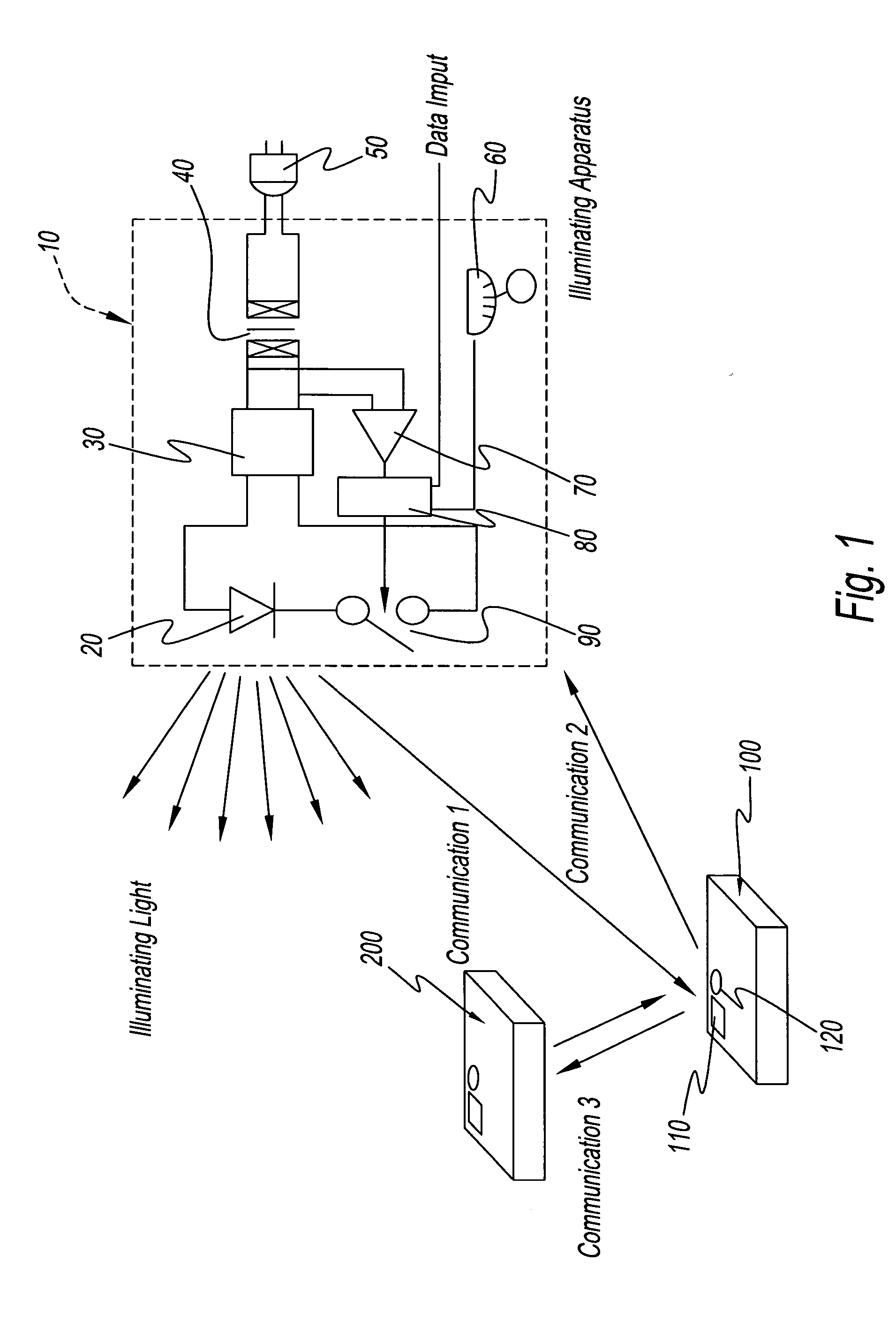
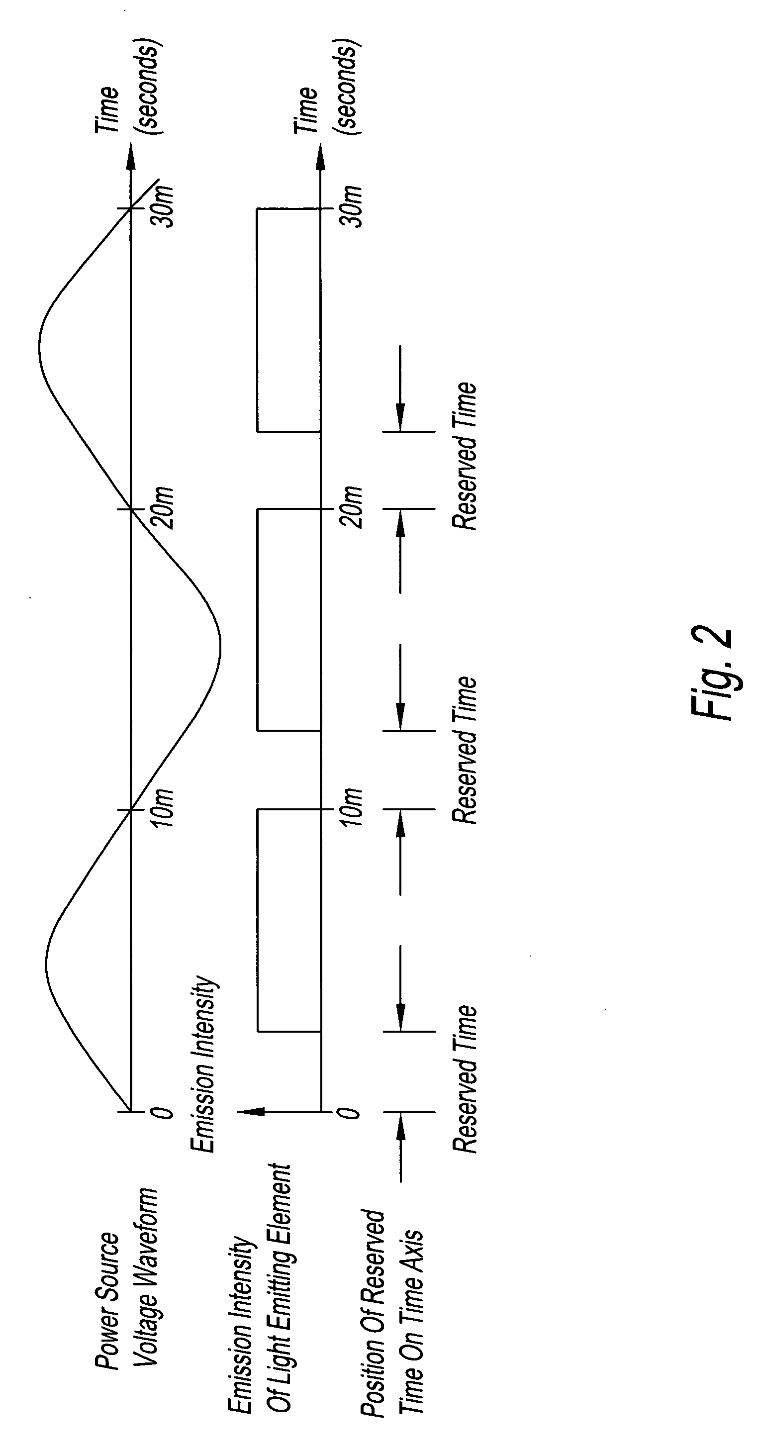
[0019] Preferred embodiments of the light communication system and the illumination apparatus therefor of the present invention will now be described in detail while referring to the attached drawings. FIG. 1 is a general diagram representing the first preferred embodiment of the light communication system of the present invention. Moreover, FIG. 2 is a time chart showing the operation of the illumination apparatus used in the present embodiment.

[0020] According to FIG. 1, the system comprises an illumination apparatus 110 and information terminals 100 and 200. Illumination apparatus 10 also functions as a communication device capable of communicating at least by visible light. For instance, illumination apparatus 10 is fastened to the ceiling of a specific room to be lighted. There are two terminals 100 and 200 in the drawing, but there can also be one terminal or three or more terminals. FIG. 1 shows the state where only terminal 100 communicates with illumination apparatus 10, b...


PUM


Abstract

An illumination apparatus is used in the light communication system. The apparatus receives electricity from a commercial alternating-current power source and a light-emitting element in the apparatus emits light. The zero passage time of commercial alternating-current power source is detected and signals are transmitted from illumination apparatus, or intercommunications between terminals of communication equipment take place, during a specific reserved time that is in synchronization with this zero passage time.

Description

1. FIELD OF THE INVENTION [0001] The present invention pertains to a light communication system, particularly a light communication system that uses an illumination apparatus for emission of visible light, as well as an illumination apparatus therefor. 2. DISCUSSION OF THE BACKGROUND ART [0002] Communication means are well known wherein infrared light or visible light is used and space serves as the signal transmission medium (see JP (Kokai) [Unexamined Japanese Patent Publication] 1[1989]-264,420). Such communication means have an advantage in that cables, fibers, and other types of wiring are not needed and this means can respond flexibly to changes in configuration, and the like. Communications in one or both directions is possible with a system whereby light emitted from a light-emitting side is received at a light-receiving side. A laser, a light-emitting diode, or another type of semiconductor device can be used as the light source. [0003] On the other hand, studies are being ...

Claims


Application Information

Patent Timeline
Patent Type & Authority Applications(United States)
IPC IPC(8): G02B27/00F21V23/04H04B3/54H04B10/11H04B10/116H04B10/118H04B10/2507H04J14/08
CPCH04B10/116H04B10/1149
Inventor YAMAMOTO, KENJI
Owner AVAGO TECH ECBU IP (SINGAPORE) PTE LTD
Learn More