
Surgical system

a surgical system and cutting device technology, applied in the field of bipolar electrosurgical cutting devices, can solve problems such as difficult control of devices by surgeons, and achieve the effect of preventing heat buildup

Inactive Publication Date: 2006-03-02
GYRUS MEDICAL LTD
View PDF15 Cites 22 Cited by
  • Summary
  • Abstract
  • Description
  • Claims
  • Application Information

AI Technical Summary

Benefits of technology

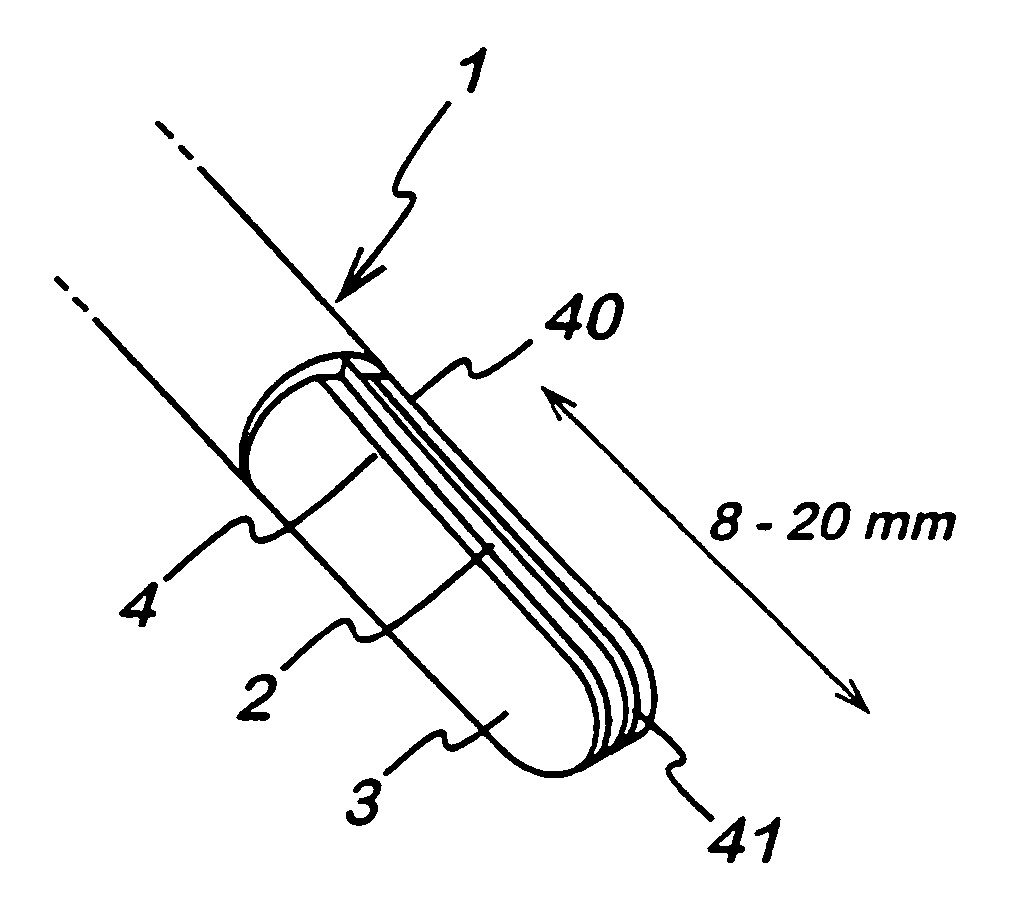
The present invention provides an improved bipolar cutting blade for use in electrosurgical procedures. The blade has first and second electrodes with a spacing between them of 0.25 mm to 3.0 mm. The electric field intensity between the electrodes is controlled to prevent direct arcing and to ensure that the active electrode is encouraged to enter the incision made by the instrument. The first electrode has a smaller cross-sectional area than the second electrode, which results in a higher initial impedance on contact with tissue and a lower rate of rise of impedance. This encourages the first electrode to become the active electrode and the second electrode to become the return electrode. The invention also provides an electrosurgical system with the improved blade and a handpiece with the blade attached.

Problems solved by technology

However, even where direct arcing between the electrodes is prevented, there is still a potential problem if the two electrodes are similar in design.
Not only does this make the device difficult for the surgeon to control (as it will be uncertain as to exactly where the cutting action will occur), but as it is likely that any particular electrode will at some time have been active.

Method used


Image

  • Surgical system
  • Surgical system
  • Surgical system

Examples


Embodiment Construction

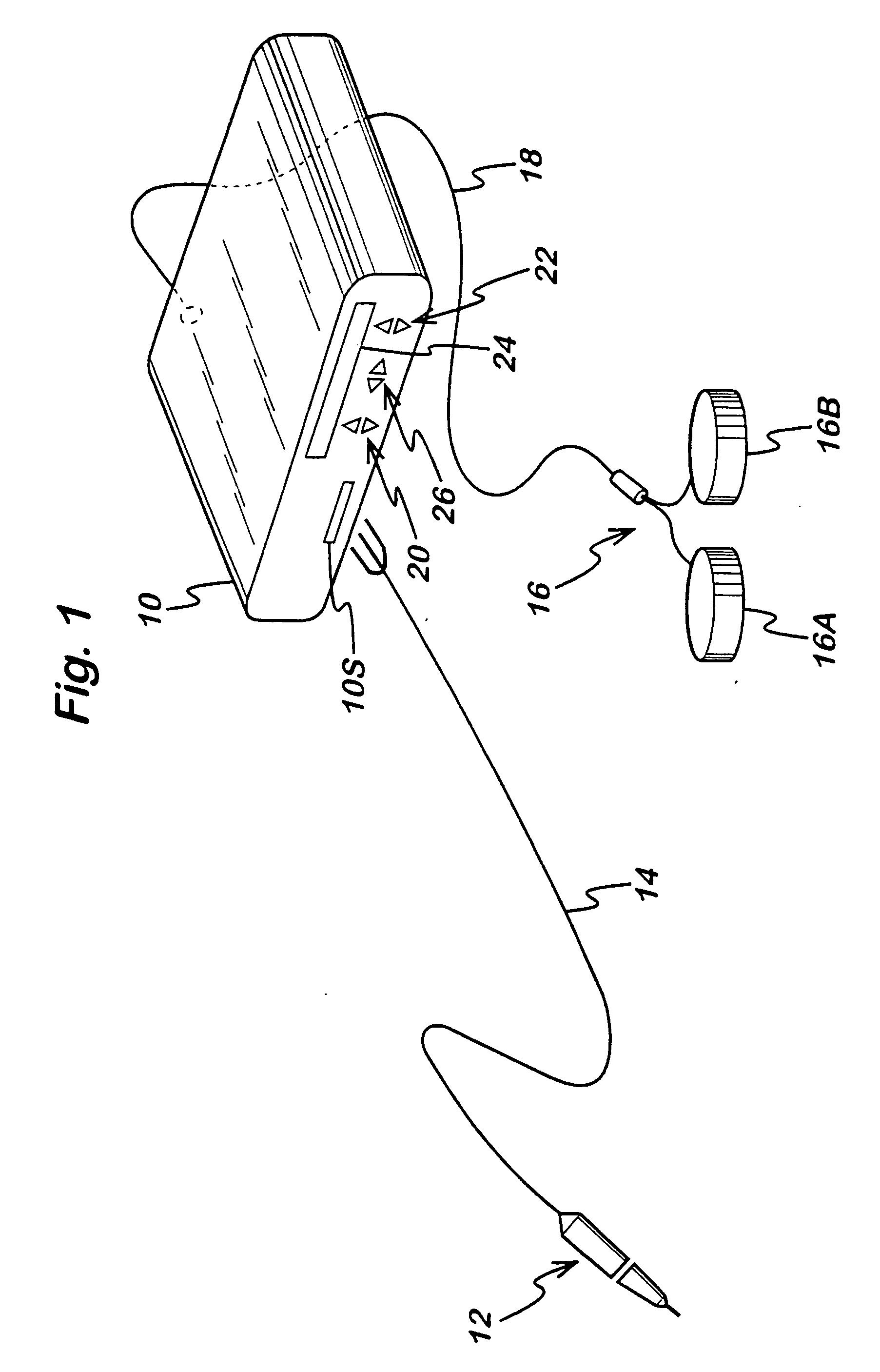
[0039] Referring to FIG. 1, a generator 10 has an output socket 10S providing a radio frequency (RF) output for an instrument 12 via a connection cord 14. Activation of the generator 10 may be performed from the instrument 12 via a connection in the cord 14, or by means of a footswitch unit 16, as shown, connected to the rear of the generator by a footswitch connection cord 18. In the illustrated embodiment, the footswitch unit 16 has two footswitches 16A and 16B for selecting a coagulation mode and a cutting mode of the generator 10 respectively. The generator front panel has push buttons 20 and 22 for respectively setting coagulation and cutting power levels, which are indicated in a display 24. Push buttons 26 are provided as an alternative means for selection between coagulation and cutting modes.

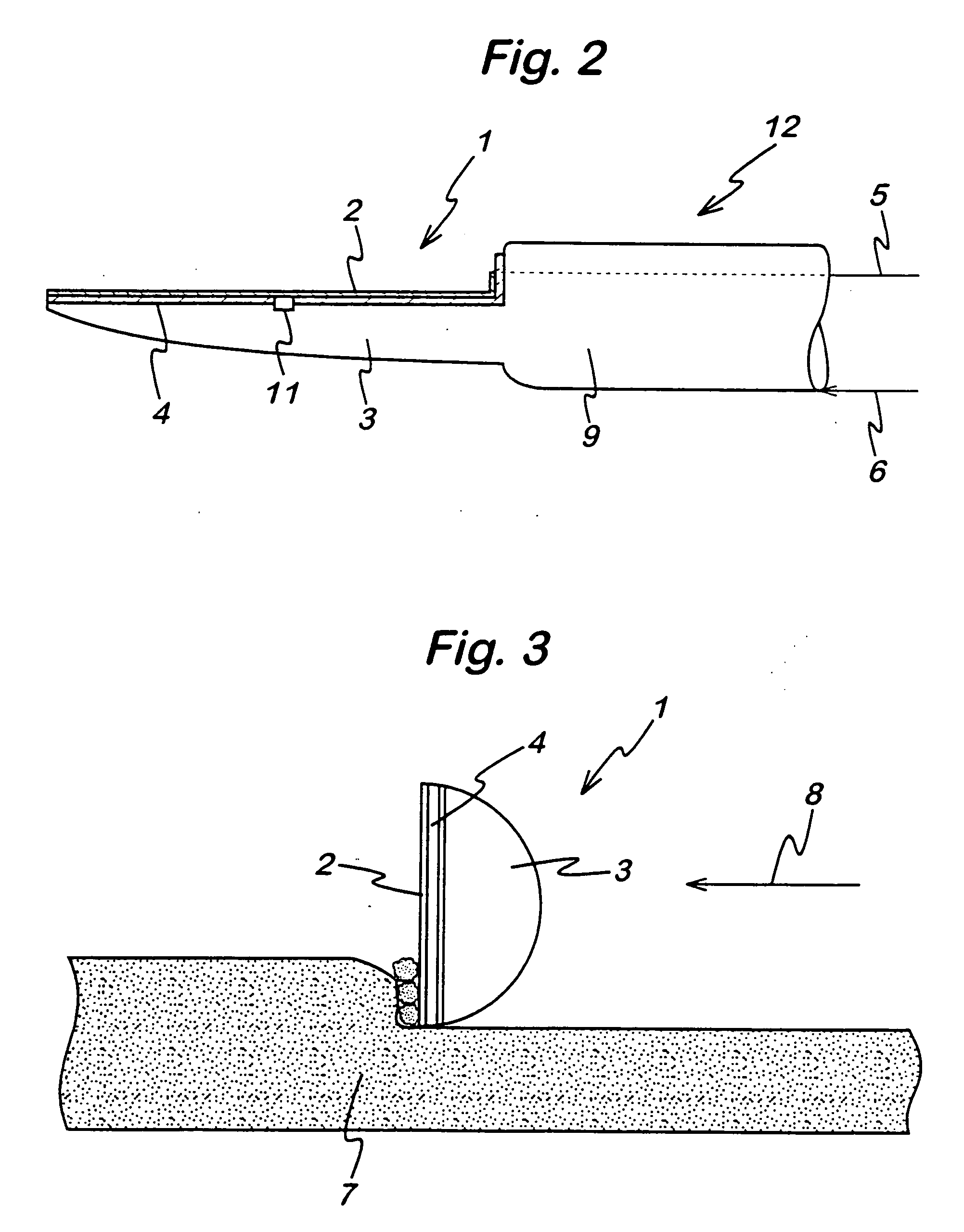
[0040] Referring to FIG. 2, the instrument 12 comprises a blade shown generally at 1 and including a generally flat first electrode 2, a larger second electrode 3, and an electrical in...


PUM


Abstract

An electrosurgical cutting blade (1) comprises a first electrode (2), a second electrode (3), and an electrical insulator (4) separating the first and second electrodes. The first and second electrodes have dissimilar characteristics (cross-sectional area, thermal conductivity etc.) such that the first electrode (2) is encouraged to become an active electrode and the second electrode (3) is encouraged to become a return electrode. The spacing between the first and second electrodes (between 0.25 mm and 3.0 mm) and the peak voltage supplied to the electrodes (2 and 3) are both selected such that arcing does not occur directly between the electrodes, but between the first electrode and the tissue at the target site. The arrangement is such that, in use, a thermal differential of at least 50° C. is established between the first and second electrodes (2 and 3), such that the second electrode is maintained below a temperature of 70° C. This is achieved either by thermally insulating the second electrode from the first electrode, and / or by transferring heat away from the second electrode, e.g. by conduction, forced cooling, or by means of a heat pipe (27).

Description

RELATED APPLICATIONS [0001] This application is a divisional of application Ser. No. 10 / 324,069, filed Dec. 20, 2002, which is a continuation in part of application Ser. No. 10 / 105,811, filed Mar. 21, 2002, now U.S. Pat. No. 6,832,998 B2, the entire contents of which are hereby incorporated by reference in this application.BACKGROUND OF THE INVENTION [0002] 1. Field of the Invention [0003] This invention relates to a bipolar electrosurgical cutting device such as a scalpel blade, and to an electrosurgical system comprising an electrosurgical generator and a bipolar electrosurgical cutting device. Such systems are commonly used for the cutting of tissue in surgical intervention, most commonly in “keyhole” or minimally invasive surgery, but also in “open” surgery. [0004] 2. Description of Related Art [0005] Electrosurgical cutting devices generally fall into two categories, monopolar and bipolar. In a monopolar device a radio frequency (RF) signal is supplied to an active electrode wh...

Claims


Application Information

Patent Timeline
Patent Type & Authority Applications(United States)
IPC IPC(8): A61B18/14
CPCA61B18/14A61B18/1402A61B2018/1412A61B2018/00023A61B2018/126A61B2018/00005
Inventor GOBLE, COLIIN C.O.BATCHELOR, KESTER J.MARSHALL, MARK G.
Owner GYRUS MEDICAL LTD
Learn More