Aseismatic support platform

a technology of aseismatic support and support plate, which is applied in the direction of shock absorbers, mechanical devices, shock proofing, etc., can solve the problems of inconvenience to our lives, serious loss of property that cannot be recovered, and personal injuries and deaths, and achieves the effect of convenient and fit assembly

Inactive Publication Date: 2006-03-09
VIO CREATION TECH CO LTD +1
View PDF0 Cites 9 Cited by
  • Summary
  • Abstract
  • Description
  • Claims
  • Application Information

AI Technical Summary

Benefits of technology

[0011] An object of the present invention is to provide an aseismatic support unit so as to be easily and fitly in-situ assembled for an equipment to be protected without discontinuing the operation of the equipment.

Problems solved by technology

Earthquake disasters occur frequently around the world, causing tremendous personal injuries and death as well as serious loss of property that cannot be recovered.
Thus, an earthquake causes not only inconveniences to our lives as a result of damages to civil constructions such as buildings and bridges, but also abruptly ceases the activities of the whole society as a result of damages to the computer networks or the common telecommunication exchanges.
However, any of these places (e.g., the computer room) is limited in space due to being full of other machines (servers).
Thus, difficulty of in-situ installation of the aseismatic system increases, and also, time for such installation is prolonged.
Furthermore, because the aseismatic systems currently available are excessively large, the in-situ installation will generally have drawbacks in the normal operation of the equipment to be protected; for example, the equipment needs to be powered off for wire reconnections.
Therefore, the clients will worry about these drawbacks and hesitate to install the aseismatic system.
In addition, the strokes will bring about very noisy sound, and also, chances of overturning the equipment being protected increase.
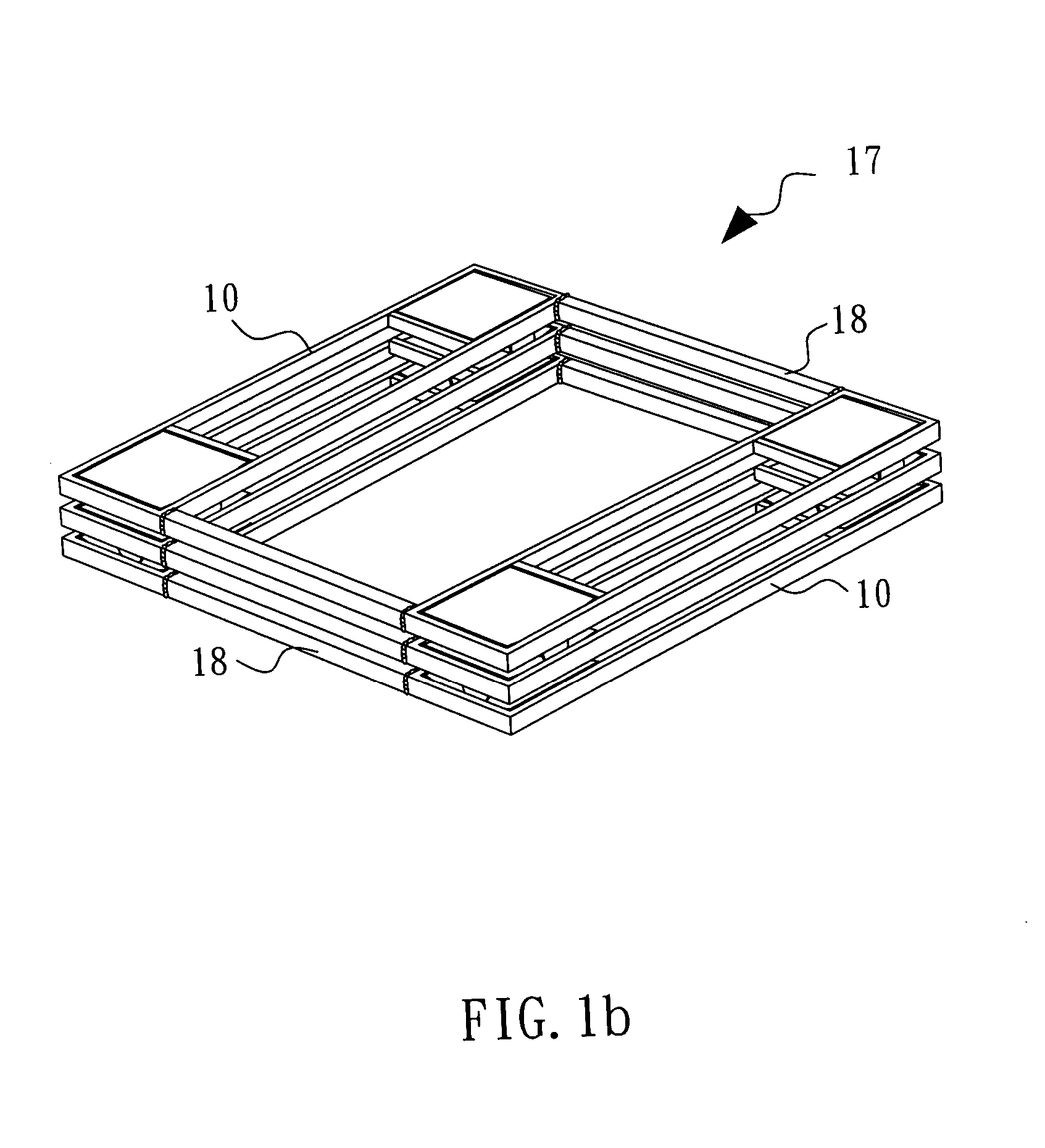
Thus, the assembled conventional aseismatic system 17 will be noticeably oversized and heavy to a certain extent.
As a result, the conventional aseismatic system 17 has difficulties in transportation thereof and complex installing procedures so that the time for the installation will be prolonged.
Therefore, services such as computer network services will be interrupted due to the installation of the conventional aseismatic system 17, causing an inconvenience to the clients and the public.

Method used


Image

  • Aseismatic support platform
  • Aseismatic support platform
  • Aseismatic support platform

Examples


Embodiment Construction

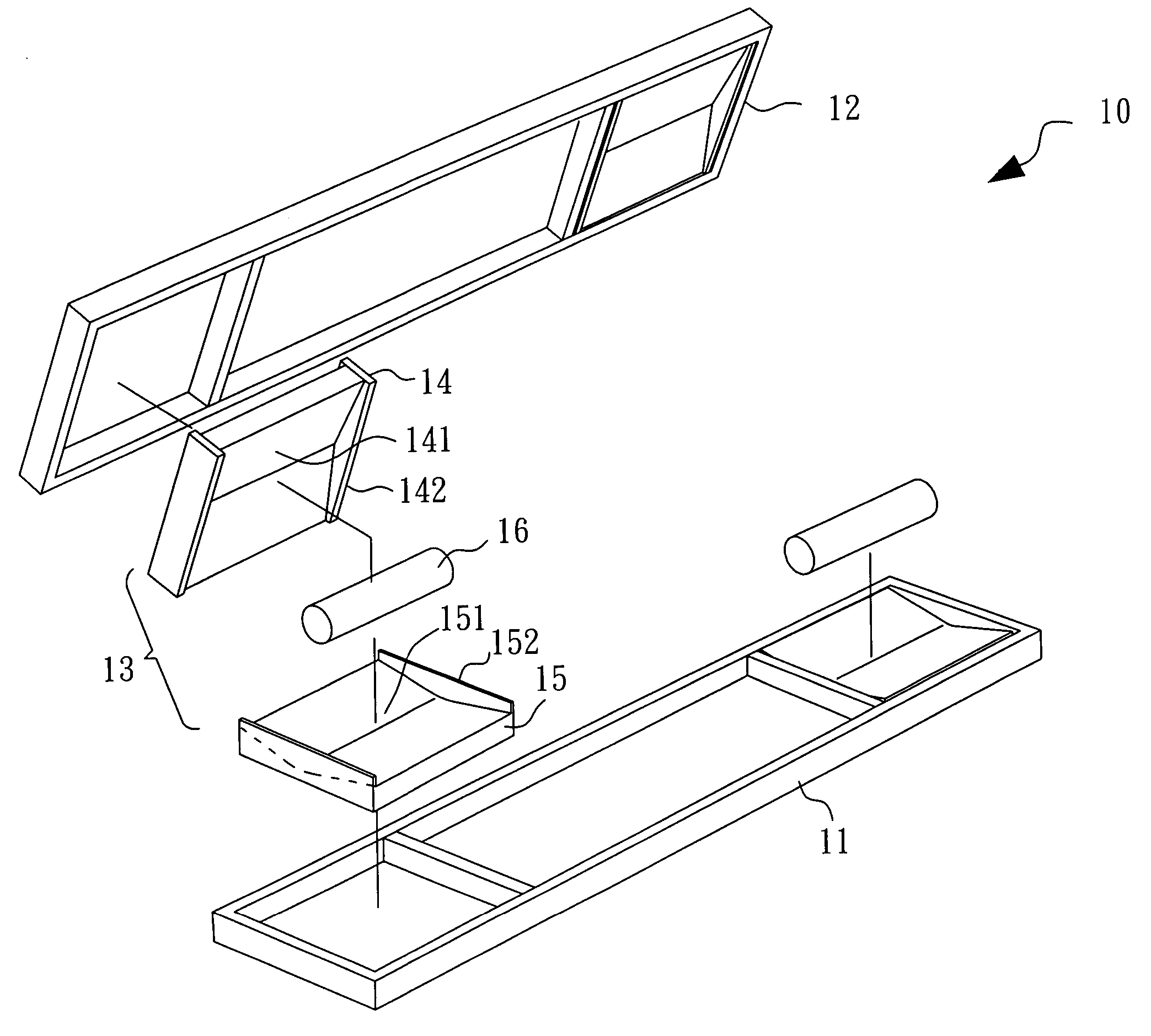
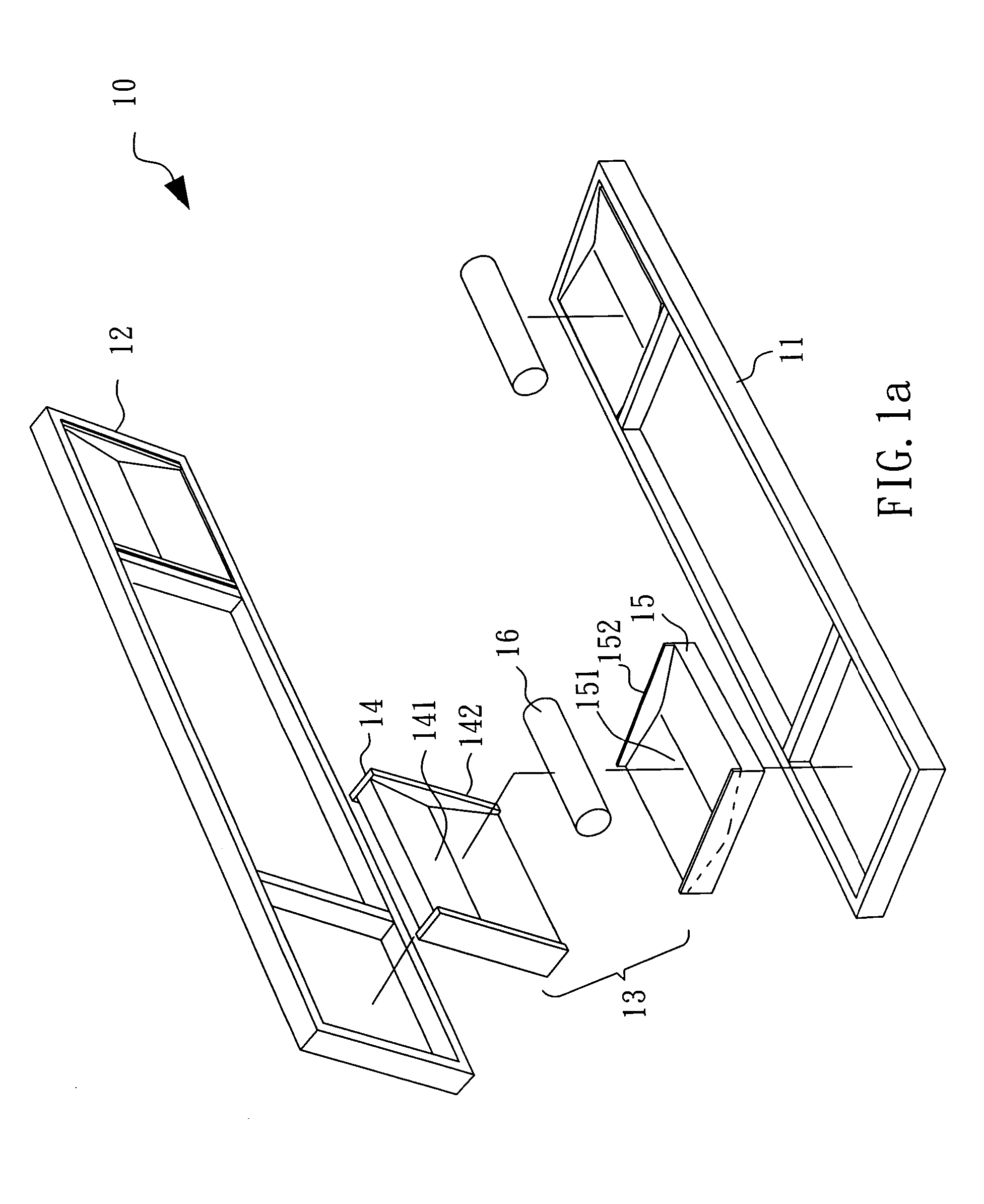
[0031] Referring to FIGS. 2a and 2b, an aseismatic unit 20 according to a preferred embodiment of the present invention is constituted by a lower support member 21, an upper support member 22 and two aseismatic units 23 each of which includes a lower carry member 25 having an upward carry surface 24, an upper carry member 27 having a downward carry surface 26 and a support roller 28 disposed between the lower carry member 25 and the upper carry member 27. The support roller 28 has a side face 281 in contact with the upward carry surface 24, the downward carry surface 26 and two ring elements 282 projecting from two ends of the side face 281 respectively to pre-define the rolling range of the support roller 28. In addition, the profile of the downward carry surface 26, viewed along a rolling direction of the support roller 28, is a U-shaped curve, facing downward, while the profile of the upward carry surface 24, viewed along a rolling direction of the support roller 28, is a U-shape...


PUM


Abstract

The present invention relates to an aseismatic support unit, and more particularly to an aseismatic support unit capable of being easily and fitly in-situ assembled to become an aseismatic system. The aseismatic support unit is mounted between a base and a loaded article, comprising a lower support member, an upper support member and a plurality of aseismatic units mounted therebetween. Each of the aseismatic units includes a lower carry member having an upward carry surface, an upper carry member having a downward carry surface and a support roller mounted therebetween. When an earthquake happens, shakes are transmitted from the base. Then, the aseismatic support unit of the present invention diminishes the extent of the shakes of the load article placed over the upper support member and thus prevent the loaded article from overturn and damage as a result of the earthquake.

Description

BACKGROUND OF THE INVENTION [0001] 1. Field of the Invention [0002] The present invention relates to an aseismatic support unit, and more particularly to an aseismatic support unit capable of being easily and fitly in-situ assembled to become an aseismatic system. [0003] 2. Description of Related Art [0004] Earthquake disasters occur frequently around the world, causing tremendous personal injuries and death as well as serious loss of property that cannot be recovered. Nowadays, the industrial and commercial communities rely heavily on exchange of a great deal of data to perform various industrial and commercial activities either by computer networks or common telecommunication exchanges. In addition, the infrastructure system for supplying water, electricity, gas and transportation to meet the basic needs for the society functions also relies heavily on data by means of the computer networks or the common telecommunication exchanges to maintain their operations. Thus, an earthquake...

Claims


Application Information

Patent Timeline
Patent Type & Authority Applications(United States)
IPC IPC(8): E04H9/02F16F9/00
CPCE04H9/023
Inventor HUANG, CHIH-HUNGLEE, SEN-NANCHANG, KUO-CHUN
Owner VIO CREATION TECH CO LTD
Why Eureka
Try Eureka