Flow control device for an injection pipe string

a flow control device and injection pipe technology, which is applied in the direction of fluid removal, sealing/packing, and/or well accessories, etc., can solve the problems of inability to achieve, inability to determine the amount of detonation of the well and/or whether the charge has detonated, and inability to achieve the effect of ensuring the quality of the perforation

Active Publication Date: 2006-03-09
RESLINK
View PDF7 Cites 135 Cited by
  • Summary
  • Abstract
  • Description
  • Claims
  • Application Information

AI Technical Summary

Benefits of technology

[0014] The object of the invention is to provide an injection pipe string that, during fluid injection into a reservoir, is arranged to provide a better and more predictable control of the injection flow along the string. This causes a better and more predictable shape and movement of the resulting flood front in the reservoir, whereby an optimal stimulated reservoir recovery may be achieved.

Problems solved by technology

A substantial disadvantage of this detonation method is that it is not possible, even in a successful perforation operation, to control the geometric shape and flow section of the individual perforation.
Moreover, uncertainty often prevails as to how many charges have detonated in the well and / or whether the charges have detonated in the correct locations.
Furthermore, uncertainty exists as to whether the perforations provide sufficient quality as outflow openings.
Hence, predictable and precise control of the injection fluid energy loss, and thus its outflow rate, is not possible between the injection string and the reservoir.
The perforation operation may also cause formation-damage effects affecting the subsequent fluid injection into the reservoir.
This additional to the formation-damage effects often occurring, and is caused by the injection pressure of the fluid.
The perforation operation may also compress soft rocks to a degree greatly reducing the flow properties of the rock.
Moreover, a certain safety risk will always be related to transport, use and storage of such explosive charges.
As the hole configuration in the string is prefabricated and thereby predetermined, this method has little flexibility with respect to making subsequent changes to said hole configuration.
This provides little possibility for making such changes to the hole configuration immediately prior to inserting the string into the well.
The fact that Normally provided the string with an excess of holes also reduces the possibility of gaining optimal control of injection rates along the string.

Method used


Image

  • Flow control device for an injection pipe string
  • Flow control device for an injection pipe string
  • Flow control device for an injection pipe string

Examples


Embodiment Construction

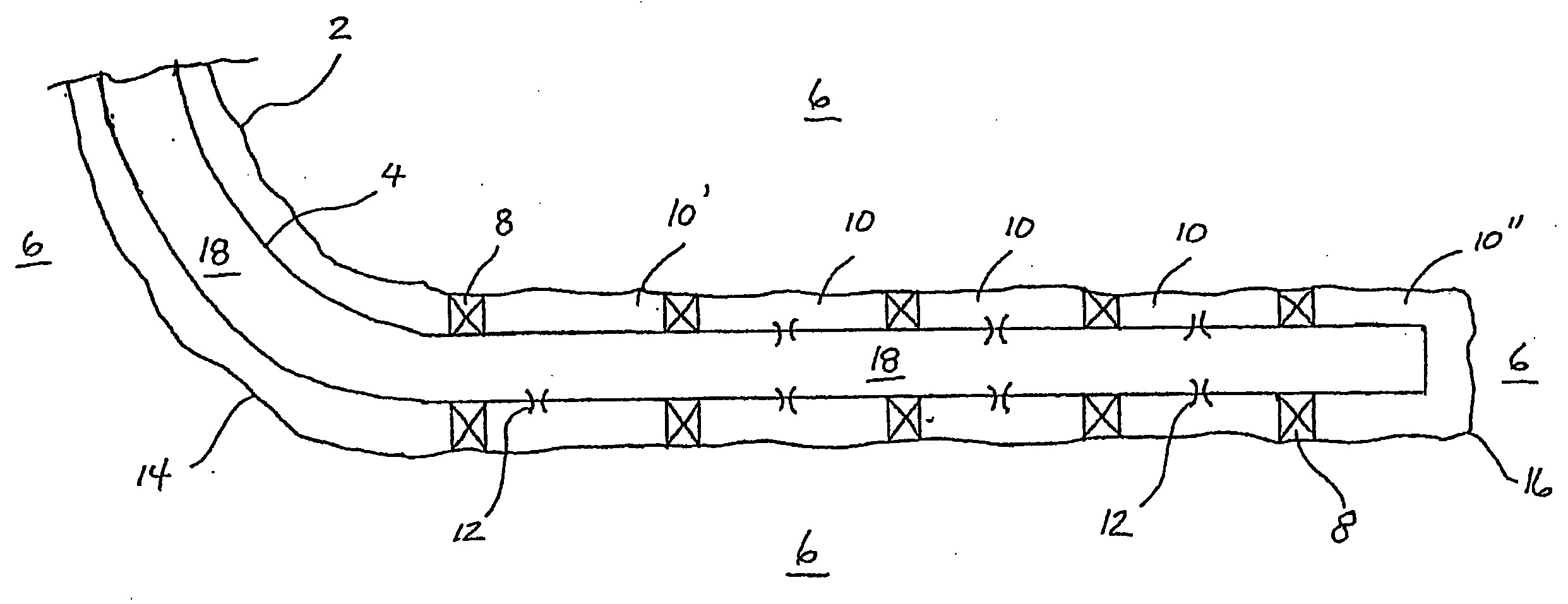
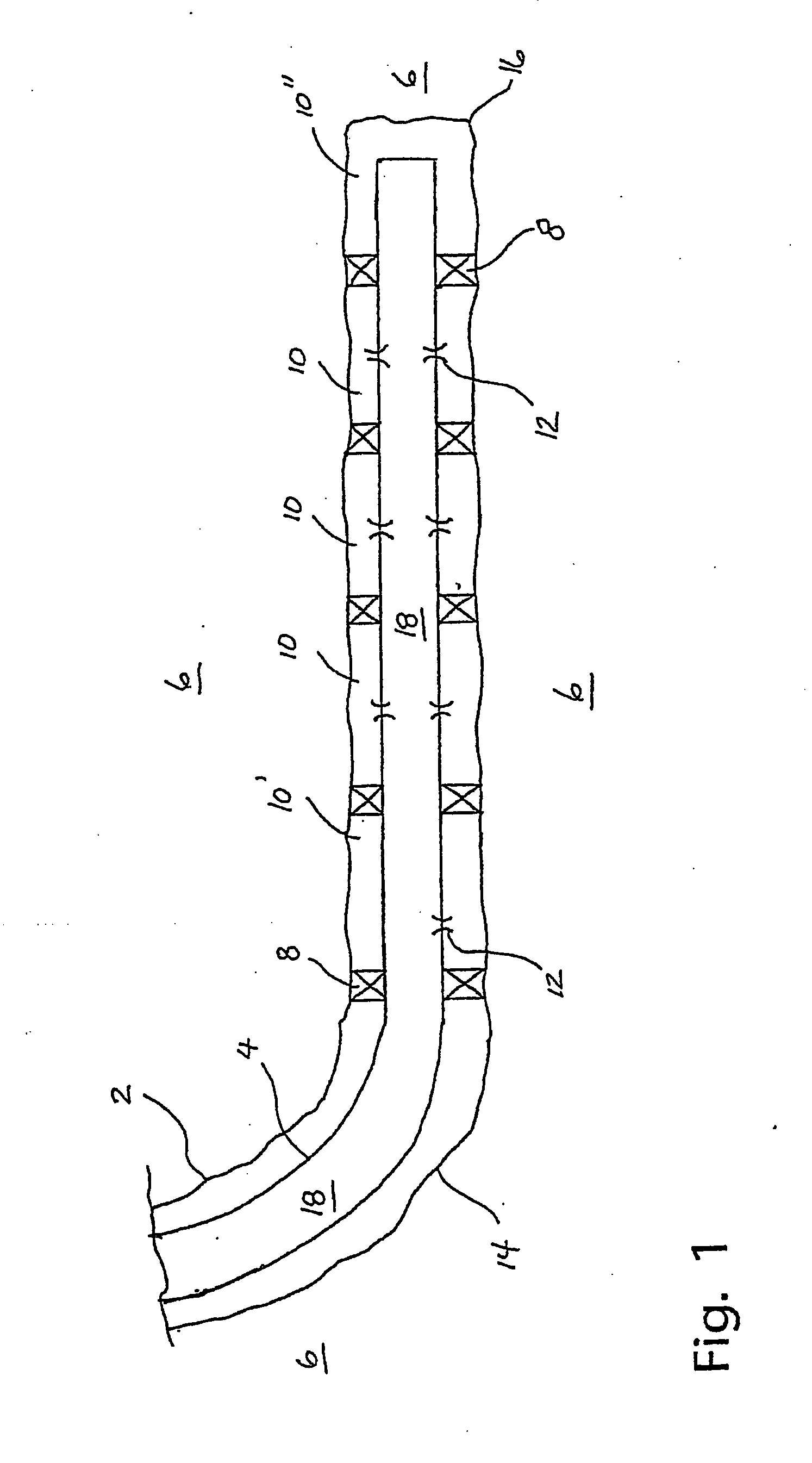
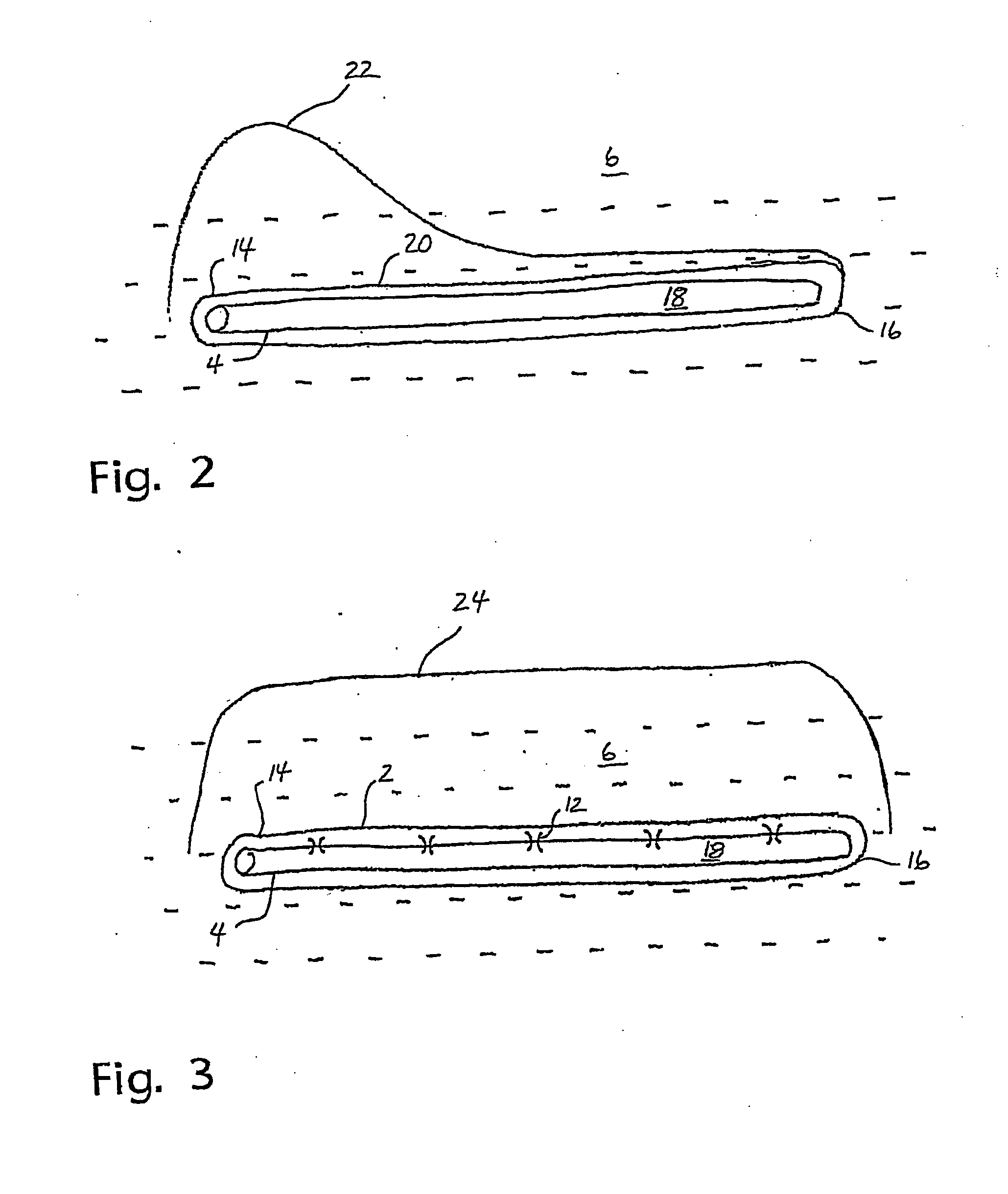
[0033]FIG. 1 shows a schematic view of a horizontal injection well 2 with its injection pipe string 4 extending through a reservoir 6 in connection with water injection into the reservoir 6. In this exemplary embodiment, and by means of external packer elements 8, the string 4 is divided into five longitudinal sections 10, thereby being pressure-sealingly separated from each other. Most longitudinal sections 10 are provided with pressure-loss-promoting flow control devices according to the invention, these consisting of, in this example, inserts 12 provided with internal nozzles. In the figure, the most upstream-located longitudinal section 10′, at the heel 14 of the well 2, is provided with fewer nozzle inserts 12 than that of the downstream sections 10, whereby the injection water from section 10′ is pressure choked to a greater degree than downstream sections thereof. However, the most downstream section 10″, at the toe 16 of the well 2, is not provided with any flow control devi...


PUM


Abstract

An injection pipe string (4) in a well (2) for the injection of a fluid into at least one reservoir (6) intersected by the string (4), in which at least parts of the injection string (4) opposite the at least one reservoir (6) are provided with one or more outflow positions / -zones. At least one pressure-loss-promoting flow control device is provided to each outflow position / -zone. In position of use, the flow control device(s) control(s) the outflow rate of the injection fluid to a reservoir rock opposite said position / zone. The flow control device(s) is (are) disposed between an internal flow space (18) of the injection string (4) and the reservoir rock opposite said position / zone, and said device(s) is (are) hydraulically connected to at least one through-going pipe wall opening (28, 86) in the injection string (4), and to said reservoir rock. By using such flow control devices, the outflow profile of the injection fluid may be appropriately controlled along the injection string (4).

Description

FIELD OF INVENTION [0001] The present invention relates to a flow control device for controlling the outflow rate of an injection fluid from an injection pipe string of a well in connection with stimulated recovery, preferably petroleum recovery. The fluid is injected from surface through well pipes extending i.a. through permeable rocks of one or more underground reservoirs, hereinafter referred to as one reservoir. Hereinafter, the pipe string through the reservoir is referred to as an injection string. The injection fluid may consist of liquid and / or gas. In stimulated petroleum recovery, it is most common to inject water. [0002] The invention is particularly useful in a horizontal, or approximately horizontal, injection well, and particularly when the injection string is of long horizontal extent within the reservoir. Hereinafter, such a well is referred to as a horizontal well. However, the invention may just as well be used in non-horizontal wells, such as vertical wells and d...

Claims


Application Information

Patent Timeline
Patent Type & Authority Applications(United States)
IPC IPC(8): E21B34/06E21B43/12E21B43/25
CPCE21B43/25E21B43/12
Inventor MOEN, TERJEKVERNSTUEN, OLES
Owner RESLINK
Why Eureka
Try Eureka