Vehicle rear seat device

a rear seat and vehicle technology, applied in the direction of movable seats, chairs, transportation and packaging, etc., can solve the problems of reducing the comfort of the vehicle, the above-described rear seat unit has some problems, and the ease of getting in and out of the vehicle, so as to improve the comfort of the vehicle, the seat is simple and the frame structure and weight reduction

Inactive Publication Date: 2006-03-09
JOHNSON CONTROLS AUTOMOTIVE SYSTEMS CORP
View PDF9 Cites 13 Cited by
  • Summary
  • Abstract
  • Description
  • Claims
  • Application Information

AI Technical Summary

Benefits of technology

[0007] The present invention is made in view of the above-described problems. An object of the present invention is to provide a vehicular rear seat unit including a seat belt attachment structure capable of surely restraining passengers, which realizes a simplified frame structure and weight reduction of a seat in addition to an improvement in comfort of a vehicle and ease in getting in and out of the vehicle.

Problems solved by technology

The above-described rear seat unit has some problems.
For example, the respective rails of the seat slide device are individually installed in the substantially transversely central parts of the one-side and the-other-side seat sections, and accordingly, impair cushioning characteristics of these seat sections, resulting in reduction of comfort of a vehicle.
Moreover, leg members fixing the respective rails of the seat slide device are located in the vicinity of doors, and hinder passengers from getting in and out of the vehicle, resulting in reduction of ease in getting in and out of the vehicle.
Accordingly, it is necessary to reinforce the bench seat for the impact load endurance, resulting in a complicated frame structure and in a weight increase of the rear seat unit.

Method used


Image

  • Vehicle rear seat device
  • Vehicle rear seat device
  • Vehicle rear seat device

Examples


Embodiment Construction

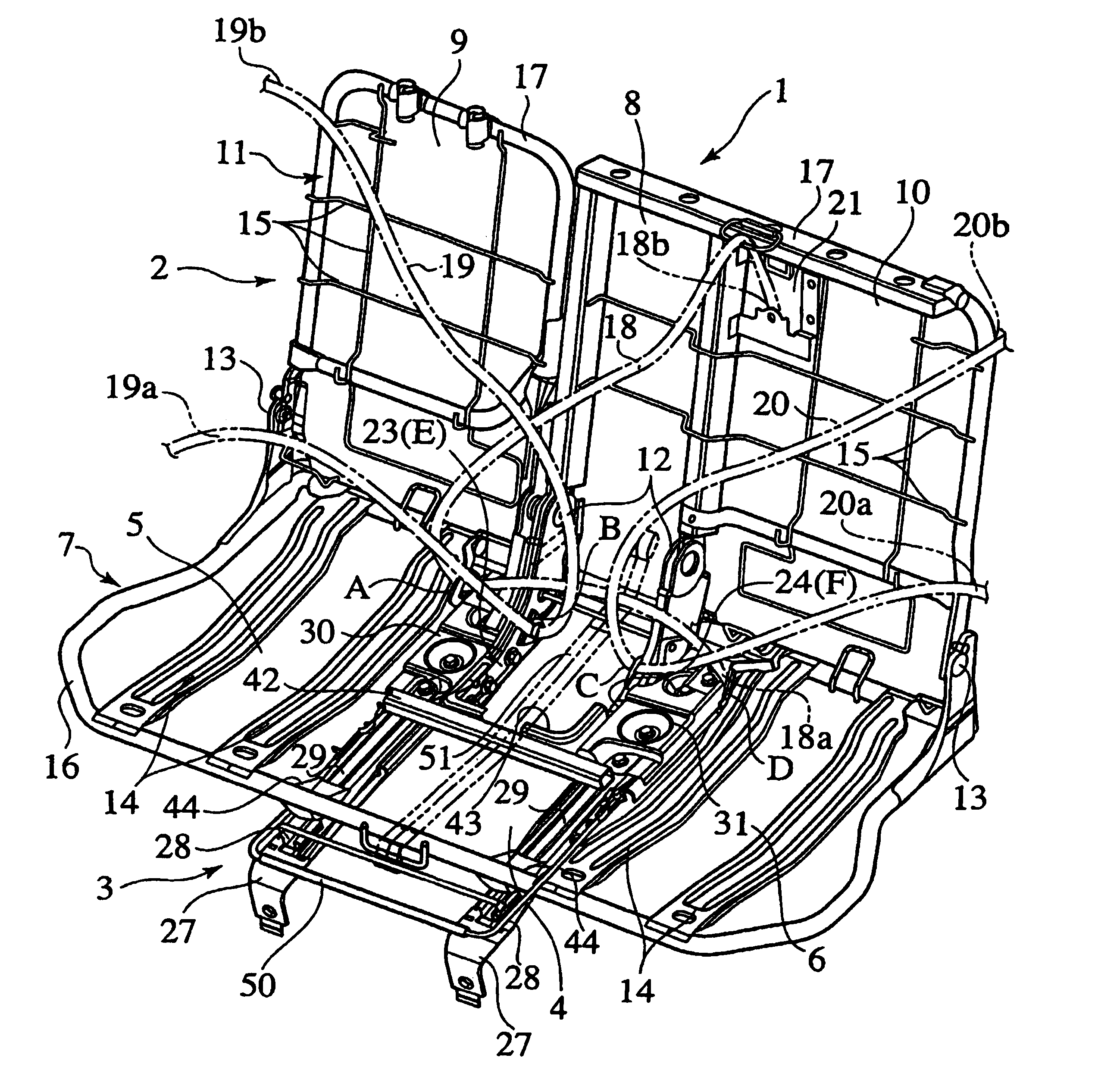
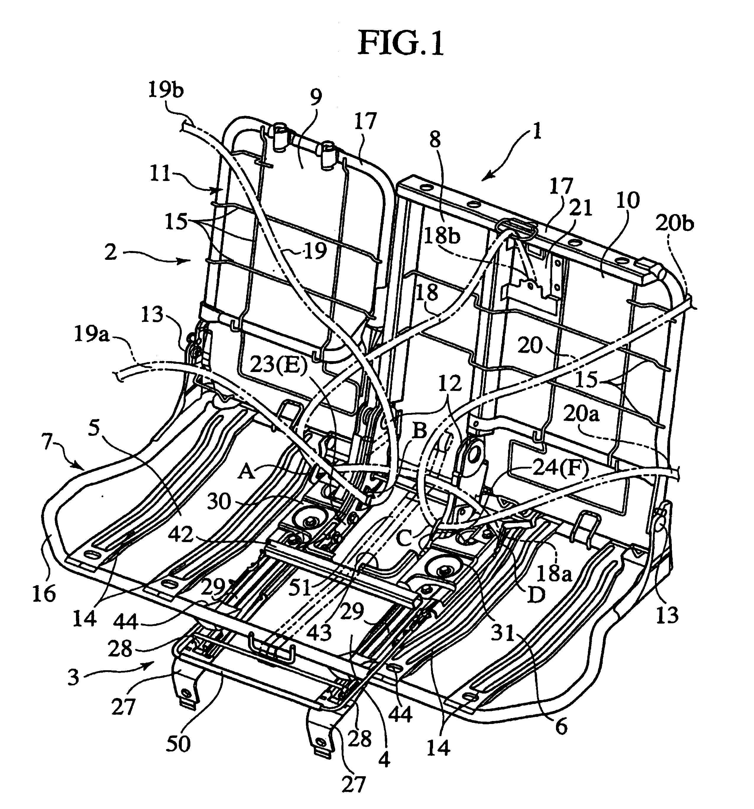
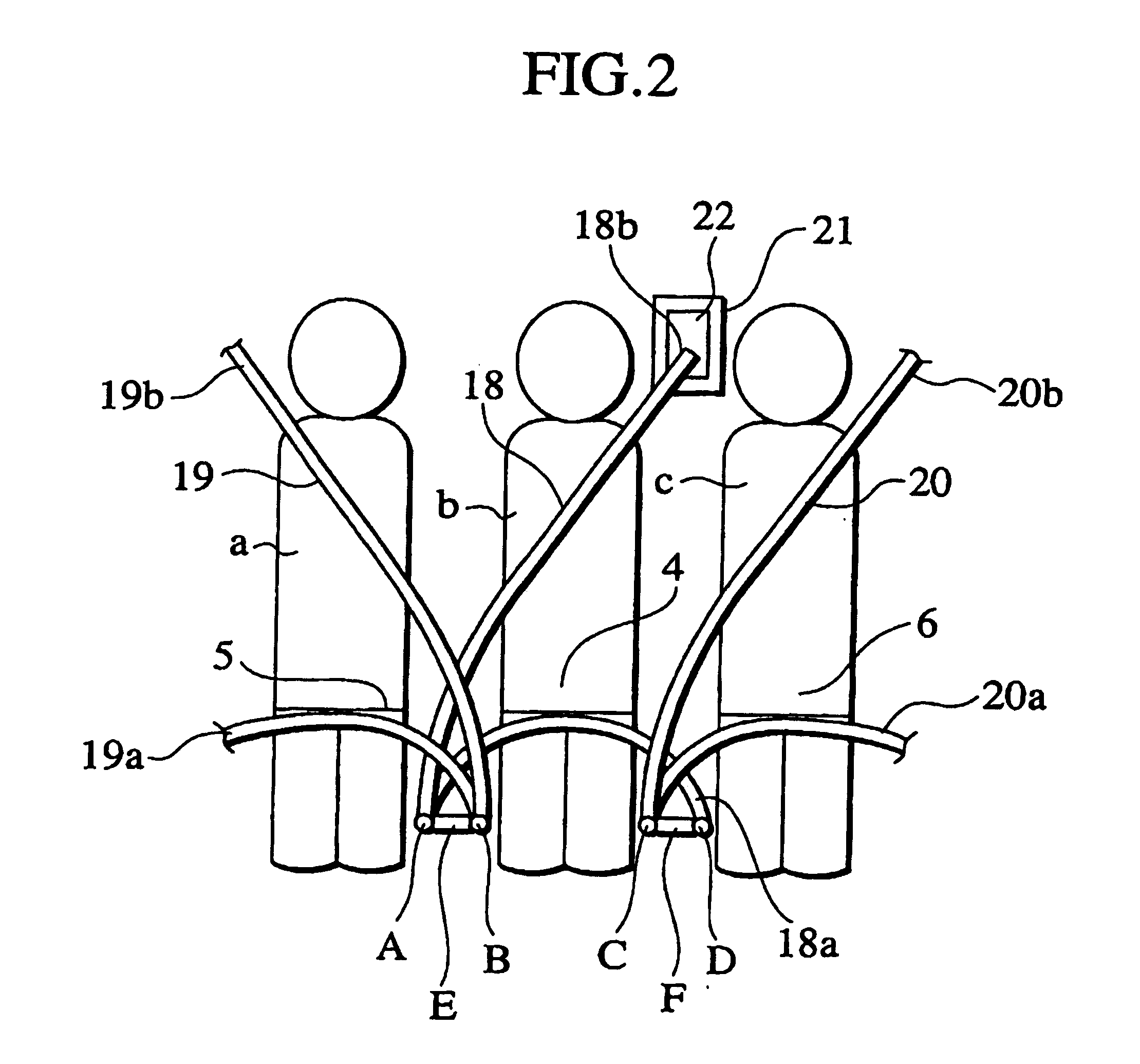
[0017] Referring generally to FIGS. 1-7, as best shown in FIG. 1, a rear seat unit 1 includes a bench seat 2, four seat belt anchors A, B, C and D, and a seat slide device 3.

[0018] The bench seat 2 includes a seat cushion 6 having a middle seat section 4, and a one-side (right-side) seat section 5 and the-other-side (left-side) seat section 7, which are provided on both right and left sides of the middle seat section 4 with the middle seat section 4 sandwiched there between, and includes a seat back 11 having a middle seat back section 8, and a one-side (right-side) seat back section 9 and the-other-side (left-side) seat back section 10, which are provided on both right and left sides of the middle seat back section 8 with the middle seat back section 8 sandwiched there between. A frame 17 of the seat back 11 is rotatably joined to a frame 16 of the seat cushion 7 with reclining devices 12 provided there between at a transversely central part of the bench seat 2 and with brackets 1...


PUM


Abstract

A vehicular rear seat unit (1) includes a bench seat (2) including a seat cushion (7) with three seat sections (4, 5, 6) arranged side by side, the seat cushion having a pair of frame members (23, 30, 24, 31) provided at positions corresponding to both side portions of the middle seat section (4); seat belt anchors (A, B, C, D) for the seat sections (4, 5, 6), the seat belt anchors (A, B, C, D) being attached to the respective frame members (23, 30, 24, 31); and a seat slide device (3) including a pair of movable rails (29) to which the respective frame members (23, 30, 24, 31) are individually fixed, and a pair of fixed rails (28) which slidably support the respective movable rails (29), the fixed rails (28) being individually fixed to a vehicle body floor.

Description

CROSS-REFERENCE TO RELATED PATENT APPLICATIONS [0001] The present Application claims the benefit of priority to the following international Applications: PCT Patent Application No. PCT / JP2003 / 005177 titled “Vehicular Rear Seat Unit” filed on Apr. 23, 2003 which published under PCT Article 21(2) on Nov. 6, 2003 as WO 03 / 091061 A1 in the Japanese language and Japanese Patent Application No. 2002-122906 filed on Apr. 24, 2002 (which are hereby incorporated herein by reference in their entirety).FIELD [0002] This invention relates to a vehicular rear seat unit in which a bench seat for three passengers is mounted on a seat slide device. BACKGROUND [0003] In a vehicular rear seat unit constructed by mounting a bench seat for three passengers, that is, a bench seat including a seat cushion having a middle seat section and right and left seat sections provided on both right and left sides of the middle seat section with the middle seat section sandwiched there between, on a seat slide devi...

Claims


Application Information

Patent Timeline
Patent Type & Authority Applications(United States)
IPC IPC(8): A47C7/02B60N2/06B60N2/12B60N2/07B60N2/08B60N2/42B60N2/68B60R22/26
CPCB60N2/065B60N2/0705B60N2/0707B60N2/0715B60N2205/35B60N2/0875B60N2/688B60R22/26B60N2/0825
Inventor YAMANAKA, SATSUKI
Owner JOHNSON CONTROLS AUTOMOTIVE SYSTEMS CORP
Why Eureka
Try Eureka