Disc guiding mechanism

Inactive Publication Date: 2006-03-09
LITE ON IT
View PDF6 Cites 0 Cited by
  • Summary
  • Abstract
  • Description
  • Claims
  • Application Information

AI Technical Summary

Benefits of technology

[0011] According to the disc guiding mechanism of the present invention, if the disc is loaded into the optical disc device in an incorrect direction, one or both hooks could not be disengaged from the teeth so that the disc would be retarded at the inlet of the device before loading into the device. Thus user could re-load the disc in a correct direction or give up to load the unsuitable disc. Therefore the disc would not be jammed in the device which causes the damage to the device.
[0014] According to the transmission element engaged with both of the first and the second sliding bars, if one of the hooks is not disengaged from the teeth array, both of the first and the second sliding bars would not slide. So that the circular disc is restricted to be loaded in a correct position, e.g. in the center of the inlet, and the non-circular disc can not be loaded into the device. It avoids the disc jammed in the device which causes the damage to the device.
[0015] According to the disc guiding mechanism of the present invention, it can load the circular disc in the correct direction and avoid the non-circular disc being loaded into the optical disc device. And it decreases the opportunity of the damage to the device caused by the disc jammed in the device.

Problems solved by technology

With the technology development, magnetic storage medium is not satisfactory to current people to transfer, store, and read a large amount of information due to its small storage capacity.
Thus, when such non-circular discs are loaded in the slot-in loading type optical disc device, it is easily jammed in the device due to its non-normalized shape and size.
It may cause the damage to the mechanism in the optical disc devise.
Moreover, even though the disc to be loaded is in a normalized shape, it also has a possibility of disc jamming due to in-correct loading direction.
If the user loads the disc in an in-correct loading direction, for example, that the loading direction is deviated from the center of the inlet for sucking the disc in, the disc positioning mechanism in the optical disc device may fail to position the disc in the correct reading position.
It may cause the disc being jammed in the device, and the mechanism in the device will be damaged.

Method used


Image

  • Disc guiding mechanism
  • Disc guiding mechanism
  • Disc guiding mechanism

Examples


Embodiment Construction

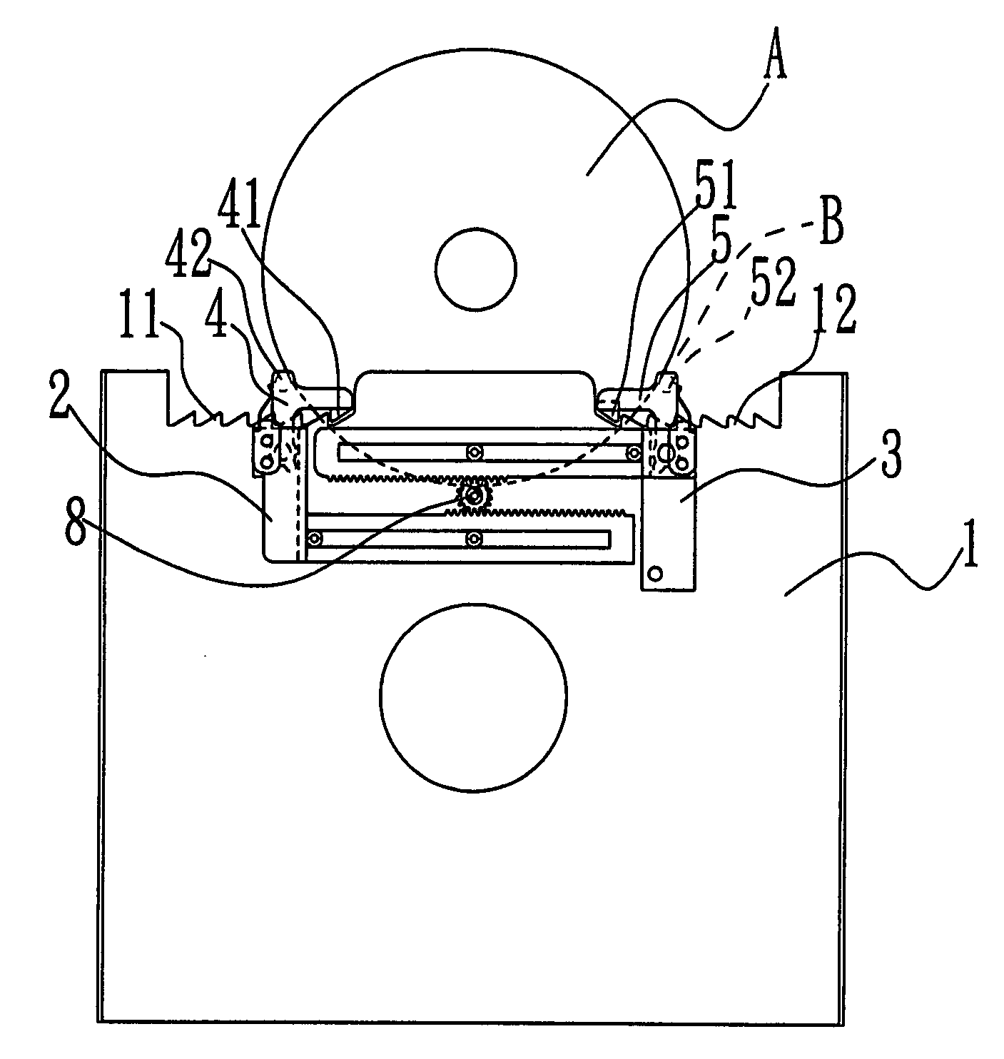
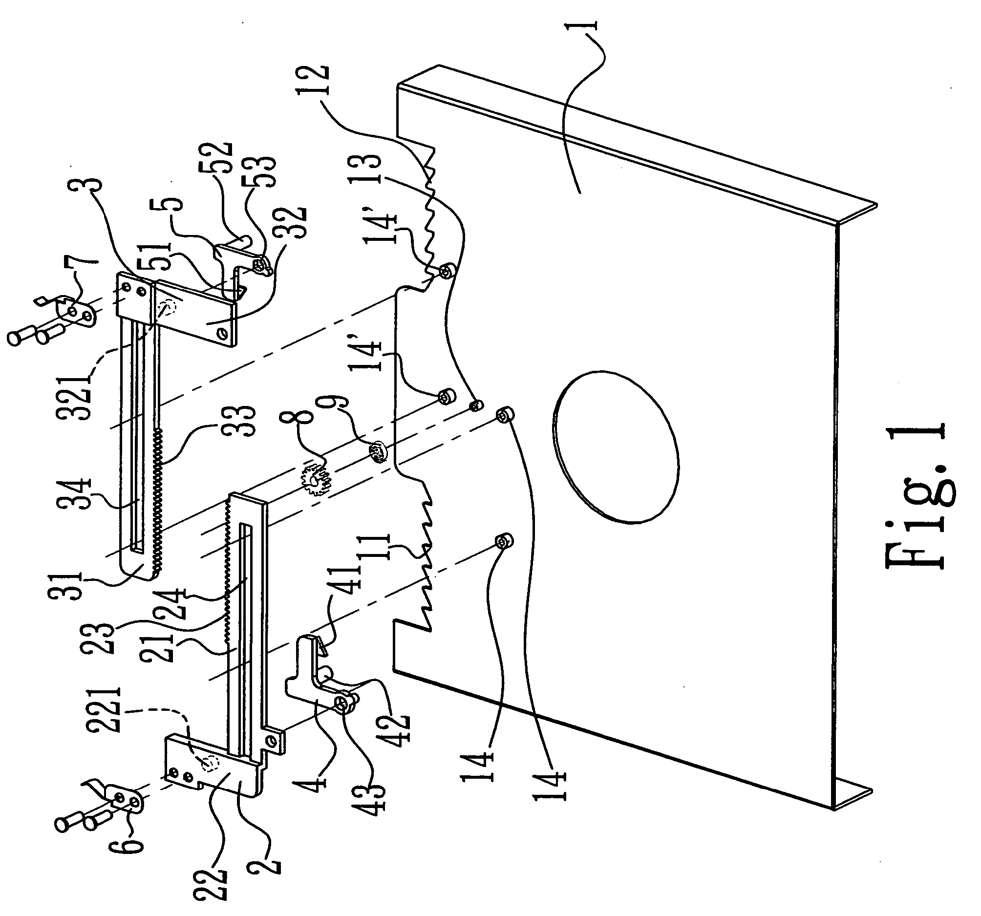
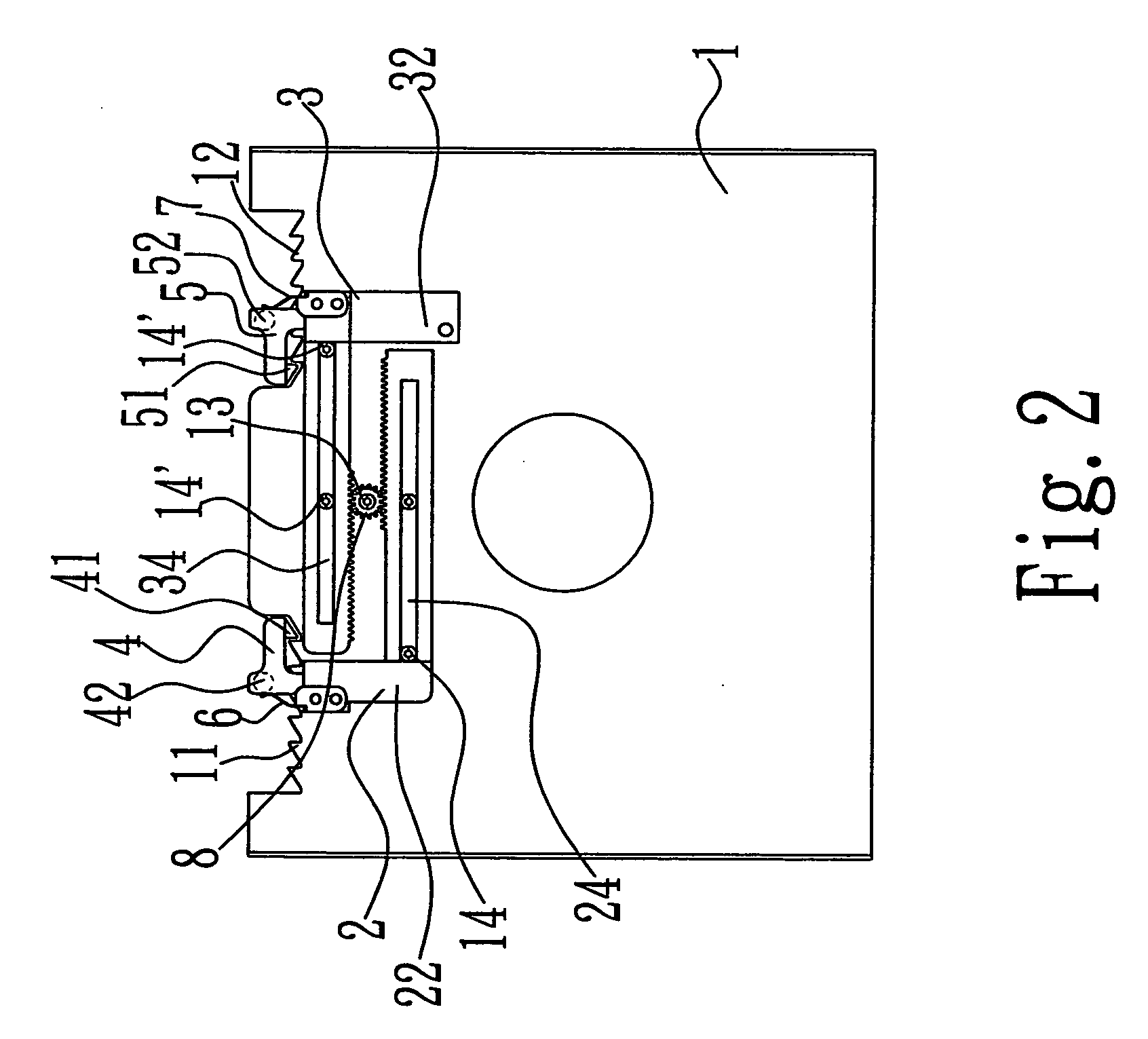
[0025] The present invention is now further illustrated by the following examples, in which the main body in the disc guiding mechanism of the present invention is a cover plate of the housing for accommodating the disc in the optical disc device, the first and the second sliding bars are positioned in the same plane, and the transmission element is a gear.

[0026]FIG. 1 is an exploding drawing showing one embodiment of the disc guiding mechanism of the present invention.

[0027] Please refer to FIG. 1, the disc guiding mechanism of the present invention mainly comprises a first sliding bar 2 and a second sliding bar 3 provided on a main body 1; a first hook 4 and a second hook 5; a first elastic member 6 and a second elastic member 7; and a transmission element (a gear) 8.

[0028] The main body 1 could be the top cover or the base board of the housing for accommodating the disc in the optical disc device. And the main body 1 is provided with teeth arrays 11 and 12 on the side to which...


PUM


Abstract

The present invention relates to a disc guiding mechanism, mainly comprising: a main body which provided with a teeth array at one side; a first and a second sliding bars both of which are provided on the main body; a transmission element provided on the main body and engaged with both of the sliding bars; a first and a second hooks rotatably provided on each sliding bar respectively; and a first and a second elastic members provided on each sliding bar to provide an elasticity on the hooks. According to the disc guiding mechanism of the present invention, a disc is guided by the hooks and carried into an optical disc device, the transmission element restricts the first and the second to slide symmetrically, so that the disc is guided and carried in a correct direction. Accordingly, a disc jamming in the optical disc device resulted from loading in incorrect direction could be avoided.

Description

[0001] This Non-provisional application claims priority under 35 U.S.C. §119(a) on Patent Application No(s). 093127207 filed in Taiwan, Republic of China on Sep. 8, 2004, the entire contents of which are thereby incorporated by reference. FIELD OF THE INVENTION [0002] The present invention relates to a disc guiding mechanism, particularly to a disc guiding mechanism provided at the inlet of a slot-in loading optical disc device. BACKGROUND OF THE INVENTION [0003] With the technology development, magnetic storage medium is not satisfactory to current people to transfer, store, and read a large amount of information due to its small storage capacity. Thus an optical disc having a large storage capability has been developed. Corresponding to the development of the optical disc, a variety of optical disc devices have been developed for reading such an optical disc. [0004] According to the disc loading type, the optical disc device can be classified as slot-in loading, cover-lifting, sin...

Claims


Application Information

Patent Timeline
IPC IPC(8): G11B17/04G11B17/03
CPCG11B17/0404
Inventor KUO, TSUNG JUNG
Owner LITE ON IT
Why Eureka
Try Eureka