Parallel haptic joystick system

a joystick and parallel technology, applied in the field of parallel haptic joystick systems, can solve the problems of small capacity, low precision, and many weak points of the series mechanism

Inactive Publication Date: 2006-03-30
KOREA INST OF SCI & TECH +1
View PDF1 Cites 55 Cited by
  • Summary
  • Abstract
  • Description
  • Claims
  • Application Information

AI Technical Summary

Benefits of technology

[0033] And, also it is preferred that the control unit is provided in the computer to which said parallel haptic joystick system is connected.

Problems solved by technology

But the series mechanism also has many weak points, e.g. lower precision because of the accumulation of errors at the articulations, and the smaller capacity because of the weak rigidity.
In particular, the inertia of the sensors and the actuators that are attached to the respective articulations, inhibit the motion of the mechanism and diminish the back drivability and the efficiency of energy consumption.
But in the haptic devices with more than 3 degree-of-freedom, the series mechanism is not preferred because of the increasing number of actuators and the accumulating errors.
The parallel mechanism has a weak point of difficult analysis and narrow work space, but has the strong points in that it endures large amount of loads because of it's structural rigidity and produces high precision because of the destructive interference of the errors.
However, such device is limited to the motions of translational 3 degree-of-freedom, only.
As a result, the motions of the above mechanisms are affected by the inertia of the actuators and the sensors.
Although above-mentioned parallel haptic master that is capable of realizing 6 degree-of-freedom motion, is superior in objective performances, it is not the most desired type of haptic device.
Considering such circumstances, to operate six actuators all the time is not a good method for the efficiency of energy consumption and control of the mechanism.

Method used


Image

  • Parallel haptic joystick system
  • Parallel haptic joystick system
  • Parallel haptic joystick system

Examples


Embodiment Construction

[0047] The preferred embodiment is illustrated in the following detailed description referring to the accompanying drawings.

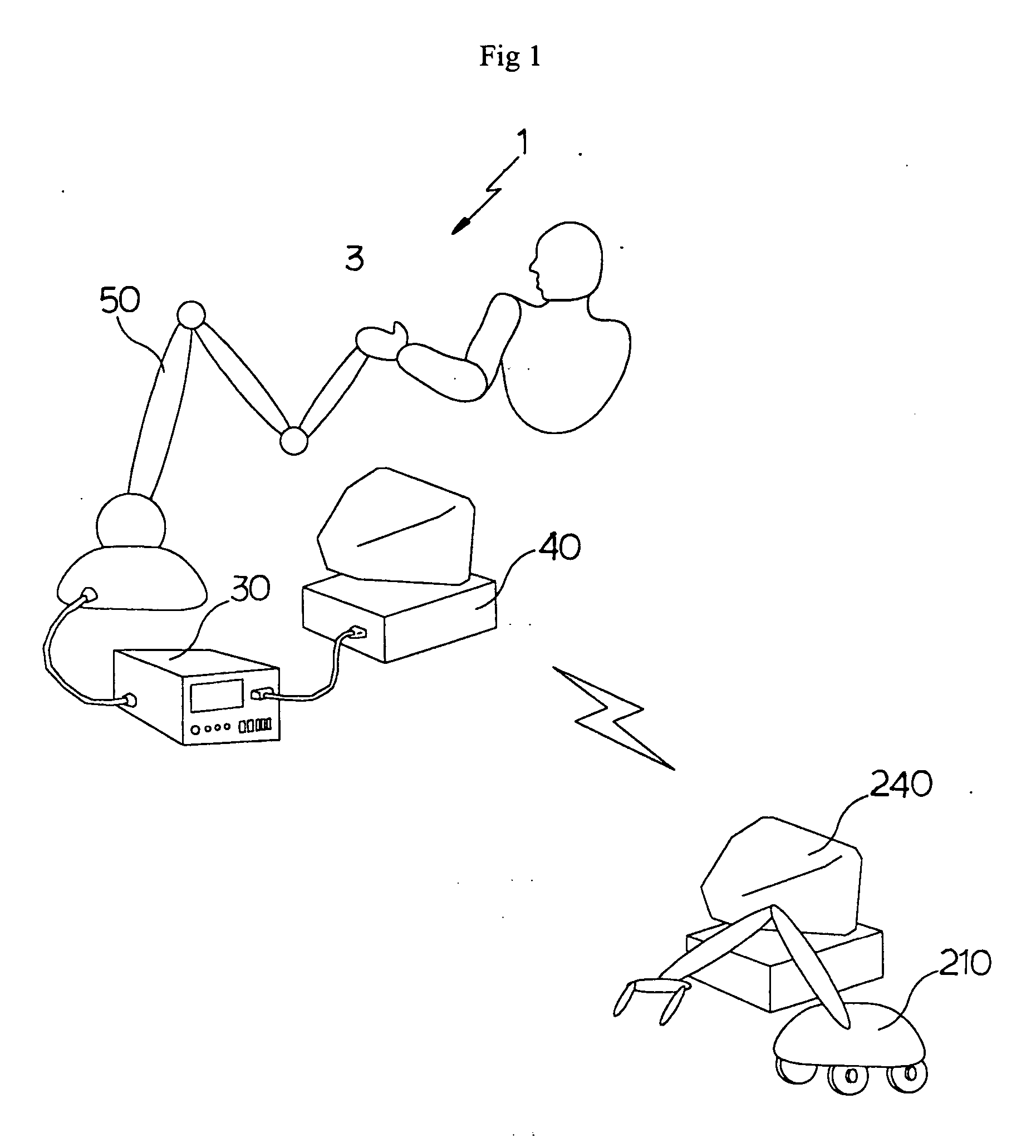
[0048]FIG. 5 is a simplified view of the haptic joystick system according to the present invention.

[0049] As illustrated in FIG. 5, the haptic joystick system 100 according to the present invention is comprised of a mechanism unit 50 with a 6 degree-of-freedoms, and a control unit 30 for inputting the location data and direction data, occurring during the operation of said mechanism unit, into computer, and manipulating said mechanism unit 50 in accordance with the outputs of the calculation of the force or torque from computer 40 for the sake of user's perception.

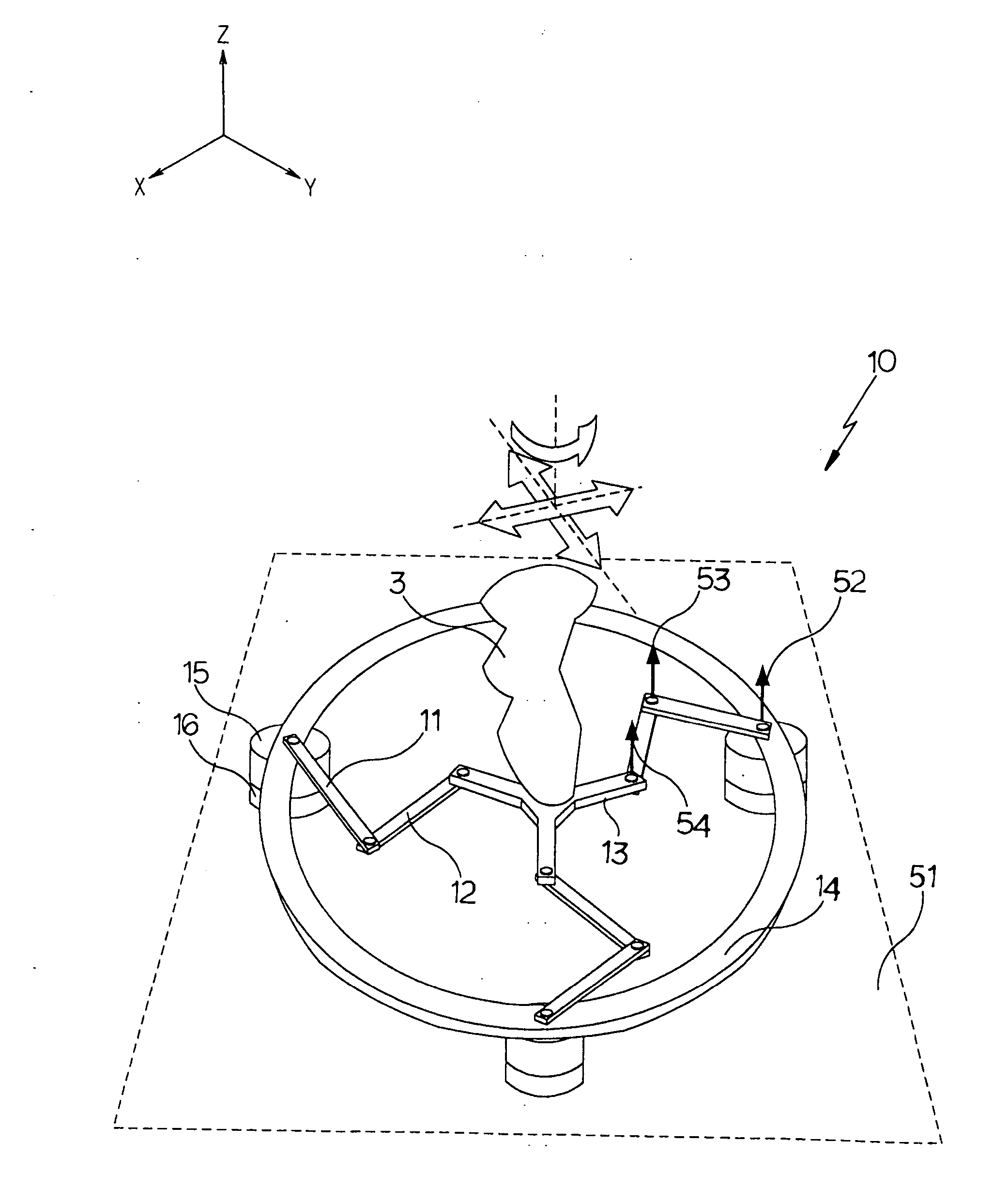
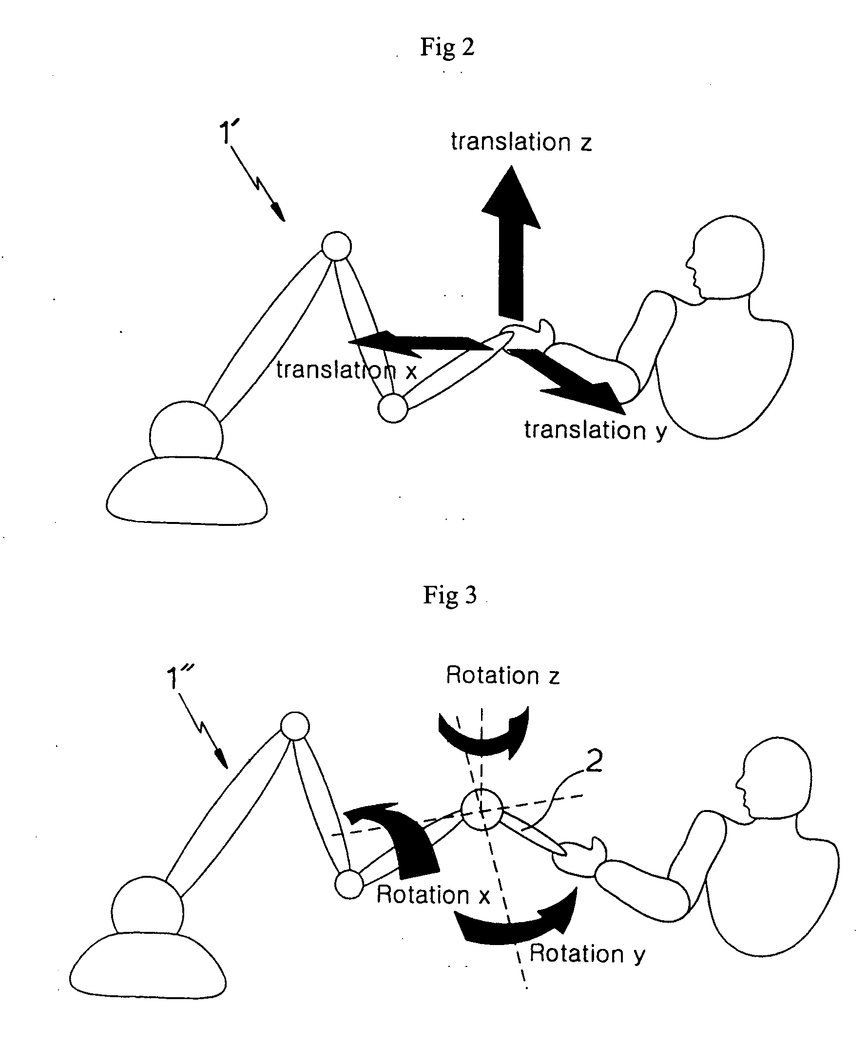
[0050] The mechanism unit 50 is comprised of a first linkage mechanism 10 capable of accomplishing 3 degree-of-freedom and a second linkage mechanism 20 capable of accomplishing 3 degree-of-freedom, which are connected in series, thus as a whole accomplishing 6 degree-of-freedom. Accordingly the me...


PUM


Abstract

The present invention relates to a haptic joystick system that is used with a computer system. The system according to the present invention includes the mechanism comprising the first link work and the second link work that respectively conduct 3 degree-of-freedom independently and are serially connected to each other. Therefore the said mechanism conducts 6 degree-of-freedom. The said mechanism is provided at its base plane with sensors and actuators, whereby not being affected by the inertia of the sensors and the actuators. Also, in the system according to the present invention, the first link work conducts 3 degree-of-freedom among the overall 6 degree-of-freedom that are frequently used in its application, and the second link work conducts another 3 degree-of-freedom. Thereby, the system according to the present invention can achieve the enhanced performance related to the energy effectiveness and the controllability.

Description

TECHNICAL FIELD [0001] The present invention relates to the 6 degree-of-freedom parallel haptic joystick system, and more specifically to the 6 degree-of-freedom parallel haptic joystick system, which is comprised of first linkage mechanism capable of planar 3 degree-of-freedom and a second linkage mechanism capable of spatial 3 degree-of-freedom, wherein the first linkage mechanism and the second linkage mechanism are BACKGROUND ART [0002] The haptic device is used for inputting the user's motion into computer by the contact with the user's body, and outputting the necessary force or feeling to the user. [0003] Unlike keyboard, mouse, joystick, monitor or printer, which are employing one way interface, the haptic device according to the present invention provides with two way interface which plays a role as a input device for inputting the user's motion into computer as well as the output device for transferring the adequate force or feelings onto the user's body following the comm...

Claims


Application Information

Patent Timeline
Patent Type & Authority Applications(United States)
IPC IPC(8): G09G5/08B25J3/00G05G5/03G05G7/02G05G7/10G05G9/047G06F3/01G06F3/033G06F3/038
CPCG05G7/02G05G9/04737G06F3/0346G06F3/0338G06F3/016G05G9/047G06F3/01
Inventor KIM, MUNSANGRYU, DONGSEOKCHO, CHANGHYUNHWANG, CHANGSOON
Owner KOREA INST OF SCI & TECH
Why Eureka
Try Eureka