Retractable shower expander assembly

a shower expander and shower technology, applied in the field of shower expanders, can solve the problems of limited practical appeal and broader application of inventions, limited use of inventions in the home, and aesthetically pleasing, and achieve the effects of increasing usable space, saving space in the bathroom, and being more aesthetically pleasing

Inactive Publication Date: 2006-04-06
BATHURST DAVID B +1
View PDF2 Cites 31 Cited by
  • Summary
  • Abstract
  • Description
  • Claims
  • Application Information

AI Technical Summary

Benefits of technology

[0008] The present invention provides a retractable shower expander assembly that is portable and can be retrofitted to an existing shower curtain and tension bar or provided as a complete assembly in combination with a shower curtain and a tension bar. The retractable shower expander assembly projects the shower curtain outwardly with a pushing force through the access opening of the shower stall or tub enclosure having a tub or base pan and selectively maintains that position during the use of the shower so as to effect an increase of usable space within the shower stall or tub enclosure by at least 50% or more. When retracted the shower curtain is pushed inwardly to conserve space in the bathroom and to be more aesthetically pleasing when hanging straight in the access opening and not in use.

Problems solved by technology

However, that invention has limitations for use in the home as it takes away usable space from the bathroom outside of the shower stall or tub enclosure and can be less aesthetically pleasing.
This severely limits the practical appeal and broader application for that invention.
Yet another drawback is that the curved shower rod requires that it be permanently mounted or affixed to the shower stall or tub enclosure walls.
In many homes this application may prove difficult or not feasible to retrofit.
Further, the curved shower rod is limited in the amount of increased shower area that it can provide.
A standard size tub having a shower stall or tub enclosure, and having a shower curtain to cover the access opening is very limited in size and comfort, as is the case in most homes over twenty or thirty years old.
A small shower stall or tub enclosure with a typical tension bar and shower curtain severely limits the movement of the users upper torso and impedes their forward and backward movement within the shower area because of the nature of the shower environment which causes the shower curtain to billow in or attach itself to the users body when it is wet.
This lack of usable area inside of a shower and the limitations of the tub and shower due to their size greatly detracts from the comfort level of the user.
Also, with persons having disabilities, or the elderly, the small shower environment is even more limiting in comfort and scope of use while showering.
For many, getting into a small shower stall or tub enclosure and then positioning and repositioning oneself inside while showering is problematic and extremely difficult for many in this state, as tub seats, hand rails and other equipment are usually necessary in the tub or shower environment to assist the handicapped or the elderly.
However, it can be very impractical to alleviate this situation, either because of the small size of the existing bathroom or that it is cost prohibitive to remodel or enlarge a small tub or shower enclosure in many of these cases.

Method used


Image

  • Retractable shower expander assembly
  • Retractable shower expander assembly
  • Retractable shower expander assembly

Examples


Embodiment Construction

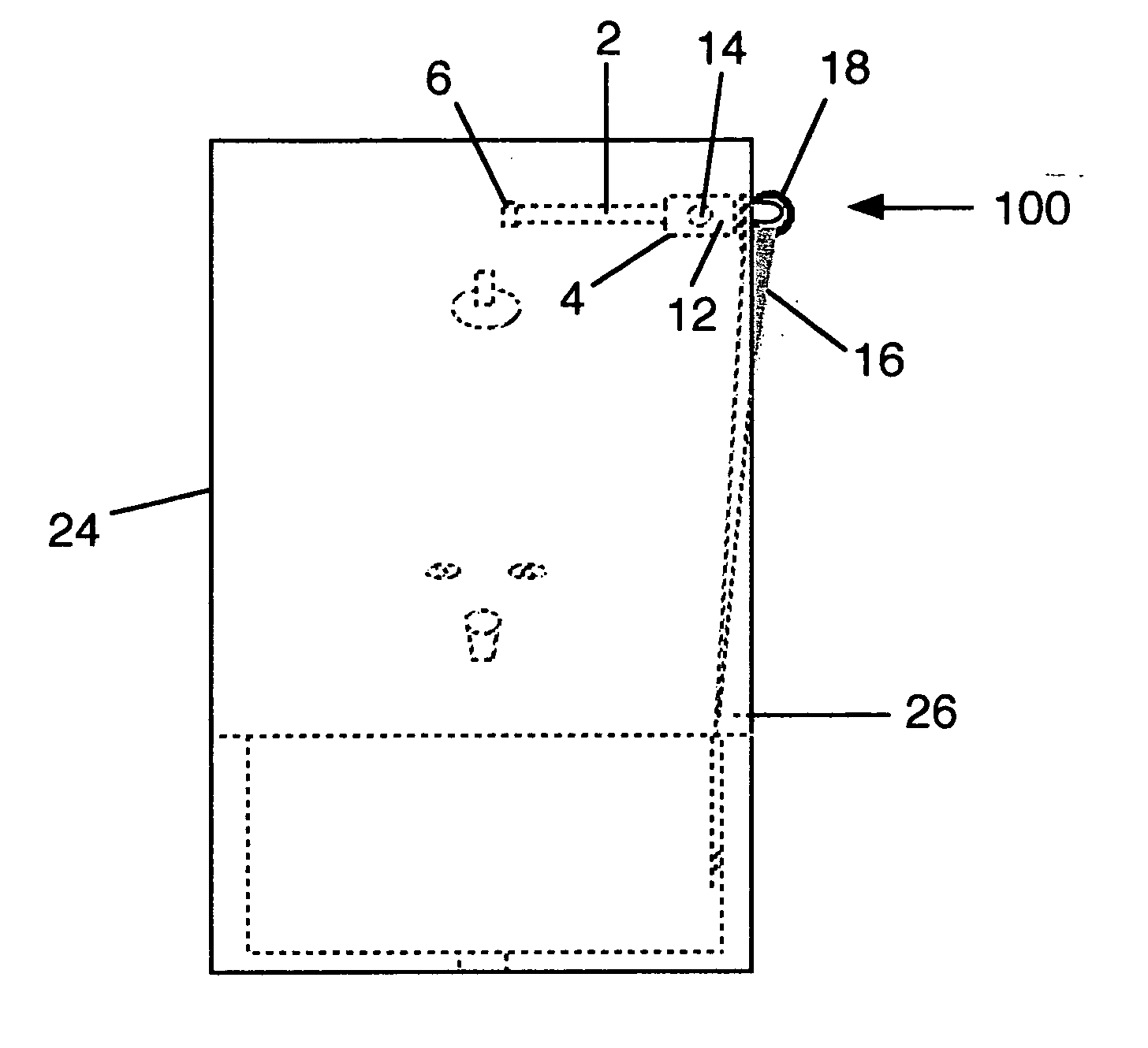
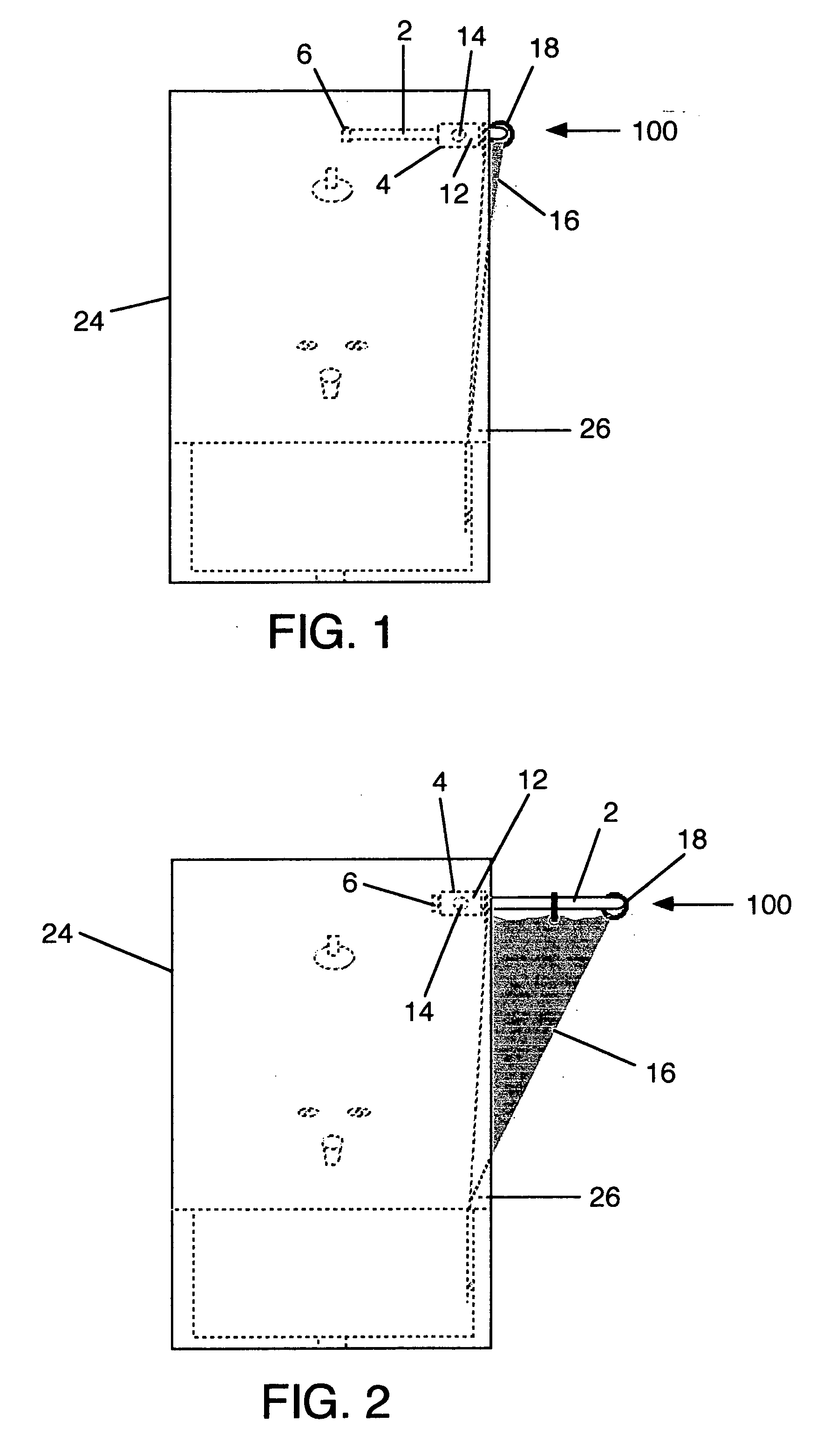
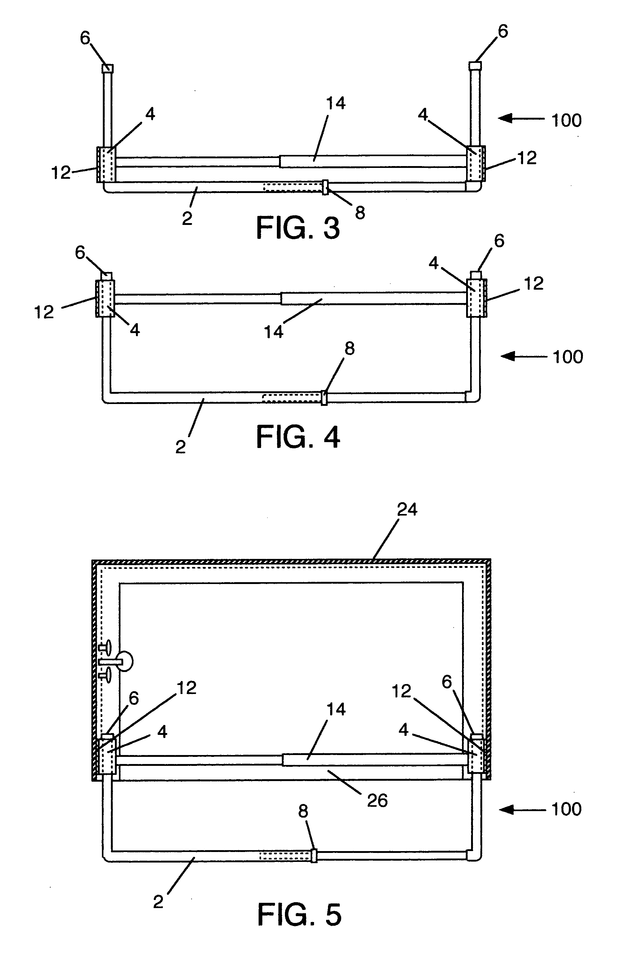
[0033] A typical shower stall or tub enclosure 24 is rectangular or square in configuration, having three walls surrounding a tub or base pan and an access opening 26 for the ingress and egress of the user. A tension rod 14 extends the width of the access opening 26 near the top and is held in place against the two end walls of the shower stall or tub enclosure 24 by tension or outward force. The tension rod 14, as is commonly well known, is typical of those used in many homes for holding a shower curtain 16 stationary between the access opening 26 of a shower stall or tub enclosure 24 for the purpose of showering or bathing and keeping the water within the tub or base pan area. The tension rod 14 has two straight lengths, a smaller one that nests, or recesses, inside of a larger one, with a spring or other mechanism inside one of the two hollow lengths, so as to make the tension rod 14 adjustable in use to accommodate various sizes of shower stall or tub enclosure 24 access opening...


PUM


Abstract

A retractable shower expander assembly for a shower stall or tub enclosure having an access opening includes a shower expander rod, two expander ports and a tension rod. The shower expander rod is formed with right angles on each end and is selectively adjustable in the middle to fit various access opening widths. The retractable shower expander assembly, being portable, is held in place by means of an adjustable tension rod, that, when enjoined inside the cavities of the two expander ports, holds the retractable shower expander assembly horizontally and fixedly in use against the two end walls of a shower stall or tub enclosure at the top of the access opening. A shower curtain is attached to the shower expander rod by hooks or rings that can slide along the shower expander rod to selectively close or open the access opening of a shower stall or tub enclosure. When outwardly force is applied to the shower expander rod the two right-angle ends extend or telescope through the apertures in the center of the expander ports and move the shower expander rod with the attached shower curtain outwardly away from the access opening to provide the maximum amount of increased area inside the shower stall or tub enclosure. When inwardly force is applied to the shower expander rod the opposite retracting or telescoping effect moves the shower curtain toward the access opening and returns it to a straight hanging position within the shower stall or tub enclosure access opening to be more aesthetically pleasing and conserve space in the bathroom.

Description

[0001] This application claims priority of Provisional Patent Application Ser. No. 60 / 616,330 filed on Oct. 6, 2004.REFERENCES CITED [0002]U.S. PATENT DOCUMENTS  699,786 A5 / 1902Campbell2,185,305 A1 / 1940Marchand160 / 1262,188,163 A1 / 1940Sherman160 / 3272,212,326 A8 / 1940Piker 4 / 5582,232,194 A2 / 1941Zogby  160 / 349.12,239,630 A4 / 1941Tendrian et al.160 / 3302,303,502 A12 / 1942 Rous 24 / 3342,313,421 A3 / 1943Dalton, Jr. 4 / 5582,454,434 A11 / 1948 Cunningham160 / 40 2,500,350 A3 / 1950Endres 4 / 1482,573,985 A11 / 1951 Porter2,608,250 A8 / 1952Meyer  160 / 349.22,613,368 A10 / 1952 Rosenbaum 4 / 6082,668,298 A2 / 1954Kimmons 4 / 6082,751,150 A6 / 1956Buccicone 235 / 98 A2,771,945 A11 / 1956 Wittrup160 / 1242,774,974 A12 / 1956 Zaloga2,840,160 A6 / 1958Tichenor  160 / 349.12,862,211 A12 / 1958 Shabarman et al.2,878,487 A3 / 1959Foote3,104,014 A9 / 1963Piette3,418,665 A12 / 1968 Long3,872,520 A3 / 1975Tyconik 4 / 1544,070,735 A1 / 1978Canaday 24 / 3044,771,517 A9 / 1988Bonanno4,754,504 A7 / 1988Cellini 4 / 1604,825,481 A5 / 1989Lonberger 4 / 6085,023,964 A6 / 1991Un...

Claims


Application Information

Patent Timeline
Patent Type & Authority Applications(United States)
IPC IPC(8): A47K3/08
CPCA47K3/30A47K3/38
Inventor BATHURST, DAVID B.BATHURST, VERONICA L.
Owner BATHURST DAVID B
Why Eureka
Try Eureka