Expandable locket

Inactive Publication Date: 2006-04-06
HUFFER HELENE
View PDF8 Cites 0 Cited by
  • Summary
  • Abstract
  • Description
  • Claims
  • Application Information

AI Technical Summary

Problems solved by technology

Some problems with earlier locket design were their bulk and their lack of reliable fasteners to keep them in a closed position.

Method used


Image

  • Expandable locket
  • Expandable locket
  • Expandable locket

Examples


Embodiment Construction

[0016] In the drawings, like numerals indicate like elements throughout. The terminology includes the words specifically mentioned, derivatives thereof and words of similar import. The embodiments illustrated below are not intended to be exhaustive or to limit the invention to the precise form disclosed. These embodiments are chosen and described to best explain the principle of the invention and its application and practical use and to enable others skilled in the art to best utilize the invention.

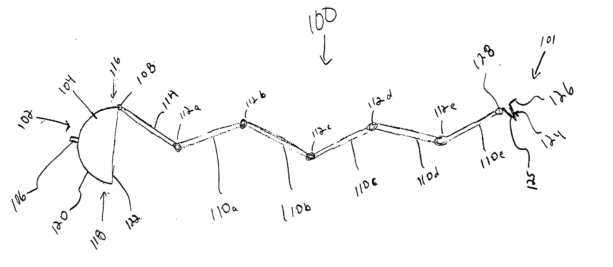
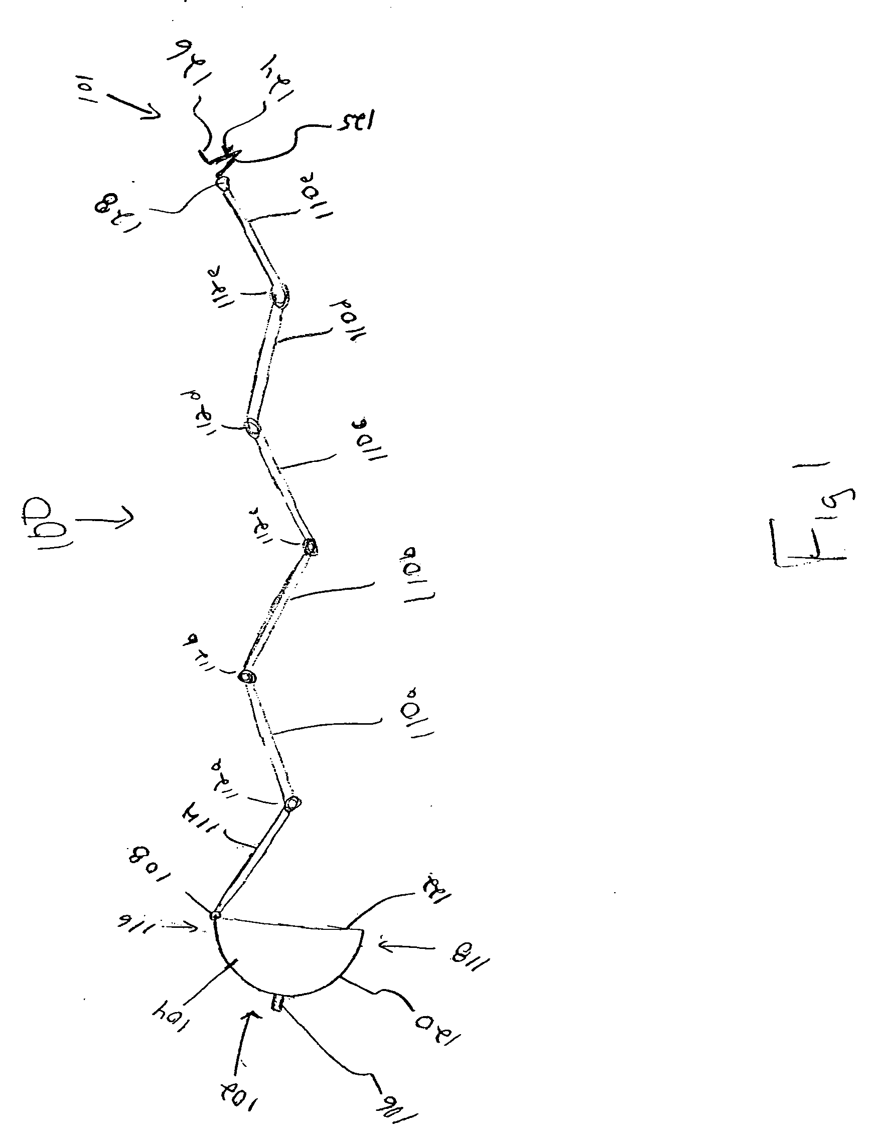
[0017] In referring to the invention, a locket 100 as shown in FIG. 1 in an open position, the term “top” shall refer to the direction that is closest to the chin of a wearer (not shown) when the locket 100 is suspended from a necklace worn around a wearer's neck. The top of the locket is disposed at the left side of the locket 100 as shown in FIG. 1. The term “bottom” shall refer to the direction away from the wear's chin, when the locket 100 is suspended from a necklace worn around a w...


PUM


Abstract

A locket having a hub, a lock and a plurality of successive hingedly connected panels is provided. The hub comprises a locking cavity having an upper wall and a lower wall. The lock has an upper biasing member and a lower biasing member. The upper biasing member and the lower biasing member are connected at a lock tip and biased away from each other. The lock is releasably, frictionally engageable with the locking cavity. The plurality of successive hingedly connected panels extends between the hub and the lock. The first panel of the successively hingedly connected panels is hingedly connected to the hub. The last panel of the successively connected panels is hingedly connected to the lock. At least one of the panels in the plurality of successive hingedly connected panels is adapted to retain a presentment therein.

Description

CROSS-REFERENCE [0001] This application is a continuation-in-part application of U.S. Design Application No. 29 / 213,103, filed Sep. 13, 2004. FIELD OF THE INVENTION [0002] The present invention relates to jewelry and ornamental apparel. Specifically, the present invention relates to lockets. BACKGROUND OF THE INVENTION [0003] For millennia, people have adorned themselves with decorative jewelry. It has been the practice of some to wear jewelry that contains the image or likeness of another, such as a loved one or family member, within. A specific type of jewelry that is used for this purpose is a locket. Lockets have been designed in many shapes and sizes. One of the most traditional designs for a locket is a simple two piece locket that opens and closes in a manner similar to that of a clam shell. The image or likeness of a person would be kept inside of the locket and would be displayed when the locket was opened and covered when the locket was closed or locked. [0004] It is often...

Claims


Application Information

Patent Timeline
IPC IPC(8): A44C15/00
CPCA44C25/004
Inventor HUFFER, HELENE
Owner HUFFER HELENE
Why Eureka
Try Eureka