Wrench having a locking device with a smaller driving angle

Inactive Publication Date: 2006-04-06
TRIANGLE INNOVATION CORP
View PDF8 Cites 0 Cited by
  • Summary
  • Abstract
  • Description
  • Claims
  • Application Information

AI Technical Summary

Benefits of technology

[0007] The primary objective of the present invention is to provide a wrench wherein the locking device includes at least two composite driving blocks having different lengths to lock and drive the drive member at different angles, so that the locking device has a smaller driving angle for driving the drive member, thereby enhancing the torque of the wrench with a smaller driving angle.
[0008] Another objective of the present invention is to provide a wrench having a simplified construction without having to changing the structure of the drive member, the drive head and the direction control knob, thereby decreasing costs of fabrication and maintenance.
[0009] A further objective of the present invention is to provide a wrench, wherein provision of the locking device does not affect the structural strength of the wrench, thereby enhancing the structural strength of the wrench.

Problems solved by technology

The number of parts makes the assembling processes to be extremely time-consuming and the parts include many different sizes and shapes which increase the manufacturing cost.

Method used


Image

  • Wrench having a locking device with a smaller driving angle
  • Wrench having a locking device with a smaller driving angle
  • Wrench having a locking device with a smaller driving angle

Examples


Embodiment Construction

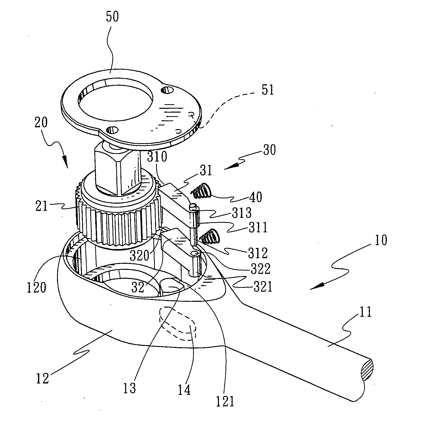
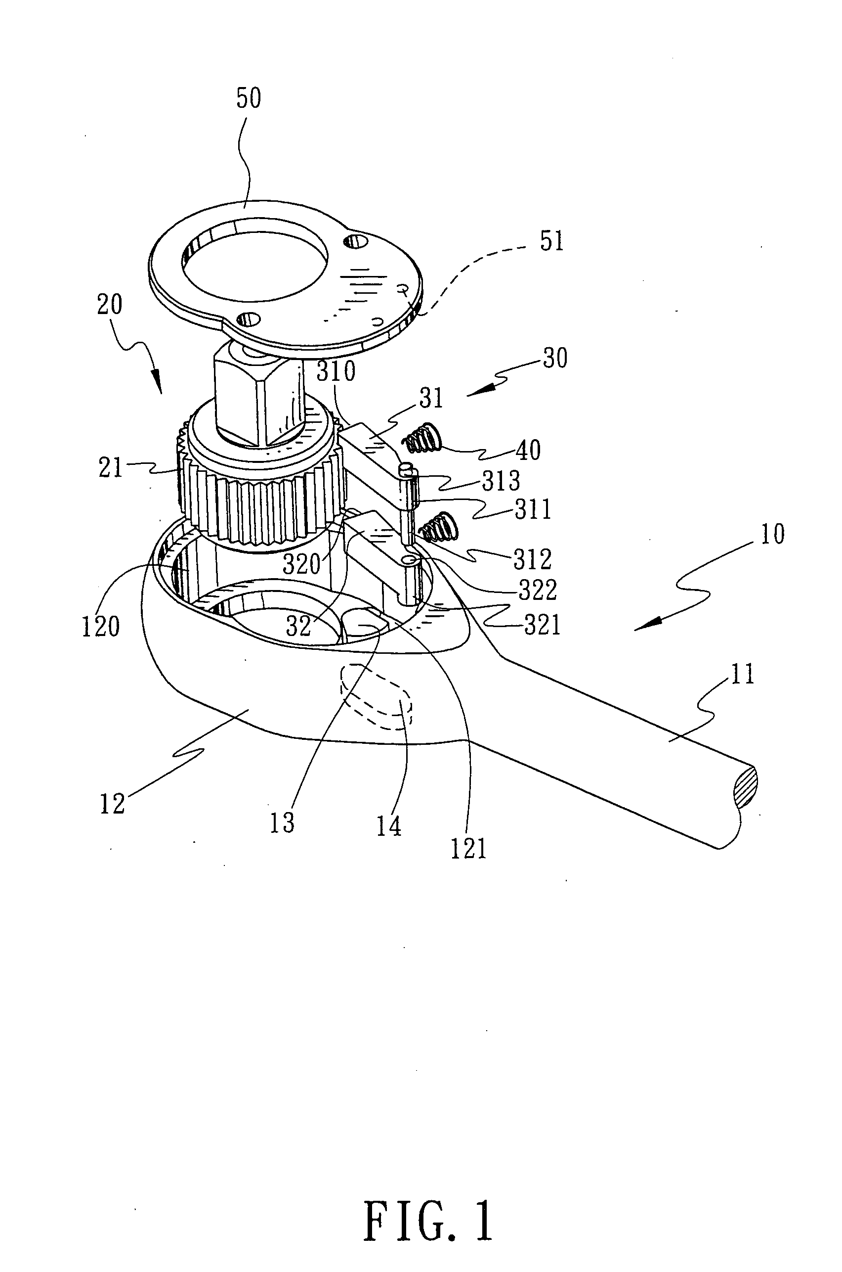
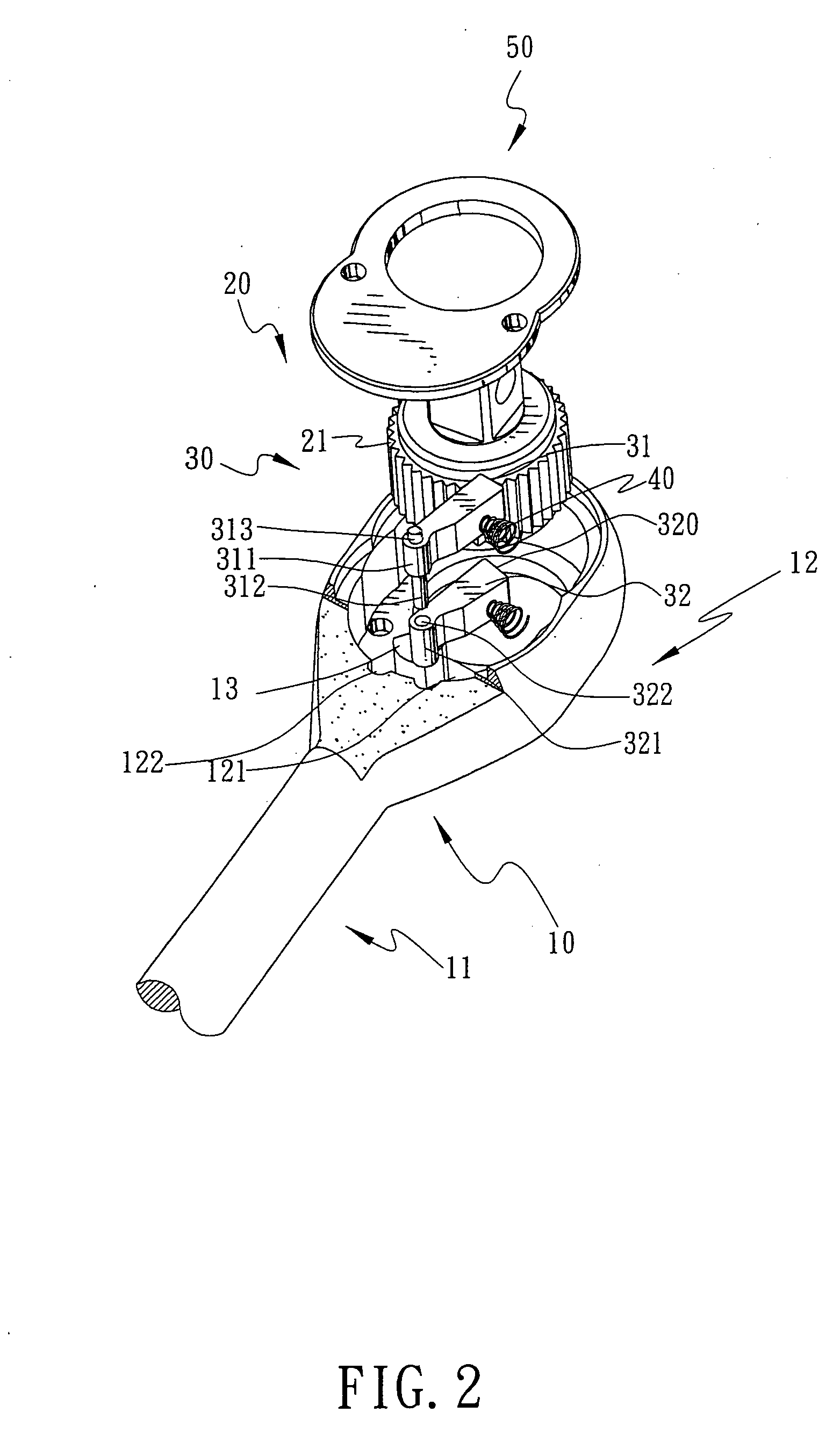
[0021] Referring to the drawings and initially to FIGS. 1-4 a wrench 10 in accordance with a first embodiment of the present invention comprises a shank 11 having an end portion formed with a drive head 12 formed with a receiving recess 120 and a driving recess 121 located beside the receiving recess 120, a drive member 20 (such as a ratchet wheel) mounted in the receiving recess 120 and having an outer wall formed with locking teeth 21, an urging block 13 mounted in the driving recess 121, two locking devices 30 mounted in the driving recess 121 and located beside the drive member 20, the urging block 13 located between the two locking devices 30, a plurality of restoring members 40 (such as springs) mounted in the driving recess 121 and urged on the locking device 30, a direction control knob 14 pivotably mounted on the drive head 12 and connected to the urging block 13 for rotating the urging block 13, and a cover 50 mounted in a top of the receiving recess 120 to cover the drive...


PUM


Abstract

A wrench includes a drive head, a drive member, a plurality of locking teeth mounted on either one of the inner wall of the drive head and the drive member, and two locking devices located beside the drive member. An urging block is located between the two locking devices for pressing one of the two locking devices to engage with the drive member. Each of the locking devices includes two driving blocks each formed with a locking end engageable with the locking teeth to drive the drive member. The locking ends of the two driving blocks are respectively engaged with the locking teeth at different time. Thus, the locking device has a smaller driving angle for driving the drive member.

Description

BACKGROUND OF THE INVENTION [0001] 1. Field of the Invention [0002] This is a Continuation-In-Part application of applicant's former patent application with application Ser. No. 10 / 382,531, filed on Mar. 7, 2003. [0003] 2. Description of the Related Art [0004] A first conventional ratchet wrench 90 in accordance with the prior art shown in FIG. 19 comprises a drive head 92 formed with a receiving recess 920 and a driving recess 921 located beside the receiving recess 920, a ratchet wheel 93 mounted in the receiving recess 920, two locking blocks 95 mounted in the driving recess 921, an urging block 94 mounted in the driving recess 921 and urged on one of the two locking blocks 95, two restoring members 96 mounted in the driving recess 921 and urged on a respective one of the two locking blocks 95, and a direction control knob 940 pivotably mounted on the drive head 92 and connected to the urging block 94 for rotating the urging block 94 to control the driving direction of the two lo...

Claims


Application Information

Patent Timeline
IPC IPC(8): B25B13/46
CPCB25B13/463
Inventor CHANG, CHUCK
Owner TRIANGLE INNOVATION CORP
Why Eureka
Try Eureka