Longitudinally-fluted multi-pole permanent-magnet rotor
- Summary
- Abstract
- Description
- Claims
- Application Information
AI Technical Summary
Benefits of technology
Problems solved by technology
Method used
Image

Examples
first embodiment
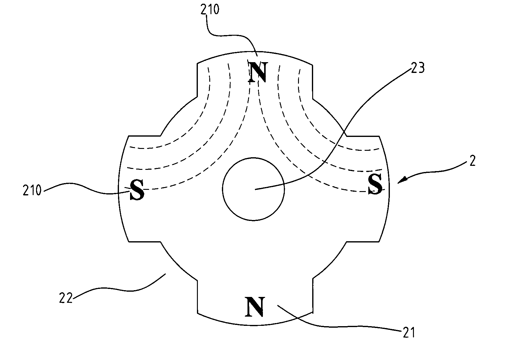
[0031] With reference to the drawings, and in particular to FIGS. 8 and 9, a longitudinally-fluted multi-pole permanent-magnet rotor constructed in accordance with the present invention, generally designated with reference numeral 2, comprises a shaft 23 having a longitudinal axis or rotational axis and an integtally-formed unitary magnetic member 21 encompassing and fixed to the shaft 23 to be rotatable in unison therewith. The magnetic member 21 forms a plurality of magnetic poles, for example four poles in the embodiment illustrated including two north poles and two south poles alternating each other, arranged along an outer circumference of the magnetic member 21. The rotor can be manufactured with any know process. As an example, the shaft 21 is provided in advance and is positioned in a cavity of a mold (not shown) in which plastics mixed with magnet powders is filled to surround the shaft 23. The plastics and magnet powder mixture is magnetized while the mixture is being cure...
second embodiment
[0035]FIGS. 11 and 12 show a rotor constructed in accordance with the present invention, which is designated with reference numeral 2′ for distinction. The rotor 2′ comprises a shaft 23′ over which an integrally formed magnetic member 21′ is tightly fit over to be rotatable in unison therewith. The magnetic member 21′ is made by compression molding and forming a plurality of angularly (or circumferentially) spaced pole sections each having a curved active outer surface 210′ separated by longitudinally (or axially) extending flutes or recesses 22′. A non-ferromagnetic material is filled in the recesses 22′ and forms a continuous, breakless cylindrical outer surface. The continuous, smooth outer surface of the rotor allows a counterpart stator to be positioned very closed to the rotor without any risk of impact therebetween during the rotation of the rotor.
[0036] A protective sheath 24′ surrounds and encloses the rotor 2′ to reduce resistance against rotation of the rotor 2′.
[0037] I...
PUM
 Abstract
Description
Claims
Application Information
 - R&D Engineer
- R&D Manager
- IP Professional
- Industry Leading Data Capabilities
- Powerful AI technology
- Patent DNA Extraction
Browse by: Latest US Patents, China's latest patents, Technical Efficacy Thesaurus, Application Domain, Technology Topic.
© 2024 PatSnap. All rights reserved.Legal|Privacy policy|Modern Slavery Act Transparency Statement|Sitemap