Rotary electric machine

Pending Publication Date: 2022-03-31
HONDA MOTOR CO LTD
View PDF27 Cites 0 Cited by
  • Summary
  • Abstract
  • Description
  • Claims
  • Application Information

AI Technical Summary

Benefits of technology

The present invention provides a rotary electric machine that reduces leakage of magnetic flux using a Halbach array of permanent magnets. This results in a smaller and lighter machine. Additionally, the arrangement of the magnets reduces interlinked magnetic flux and eddy currents, which reduces heat generation.

Problems solved by technology

In the case that the stator is incapable of sufficiently receiving such an amount of magnetic flux, a so-called leakage flux (leakage of magnetic flux) occurs.
The leakage of magnetic flux becomes a cause of generation of heat.
Further, in the case that the rotary electric machine is used as an electric generator, an improvement in the amount of generated electrical power is hindered.
In the foregoing manner, the leakage of magnetic flux leads to various inconveniences.
In this case, however, it is necessary to work or cut the interior of the rotary electric machine or to provide any members that are not directly relevant to the operation of the rotary electric machine.
Then, it is thought that making such a rotary electric machine smaller in scale and lightweight is not easy, and that it raises cost.

Method used


Image

  • Rotary electric machine
  • Rotary electric machine
  • Rotary electric machine

Examples


exemplary embodiment 1

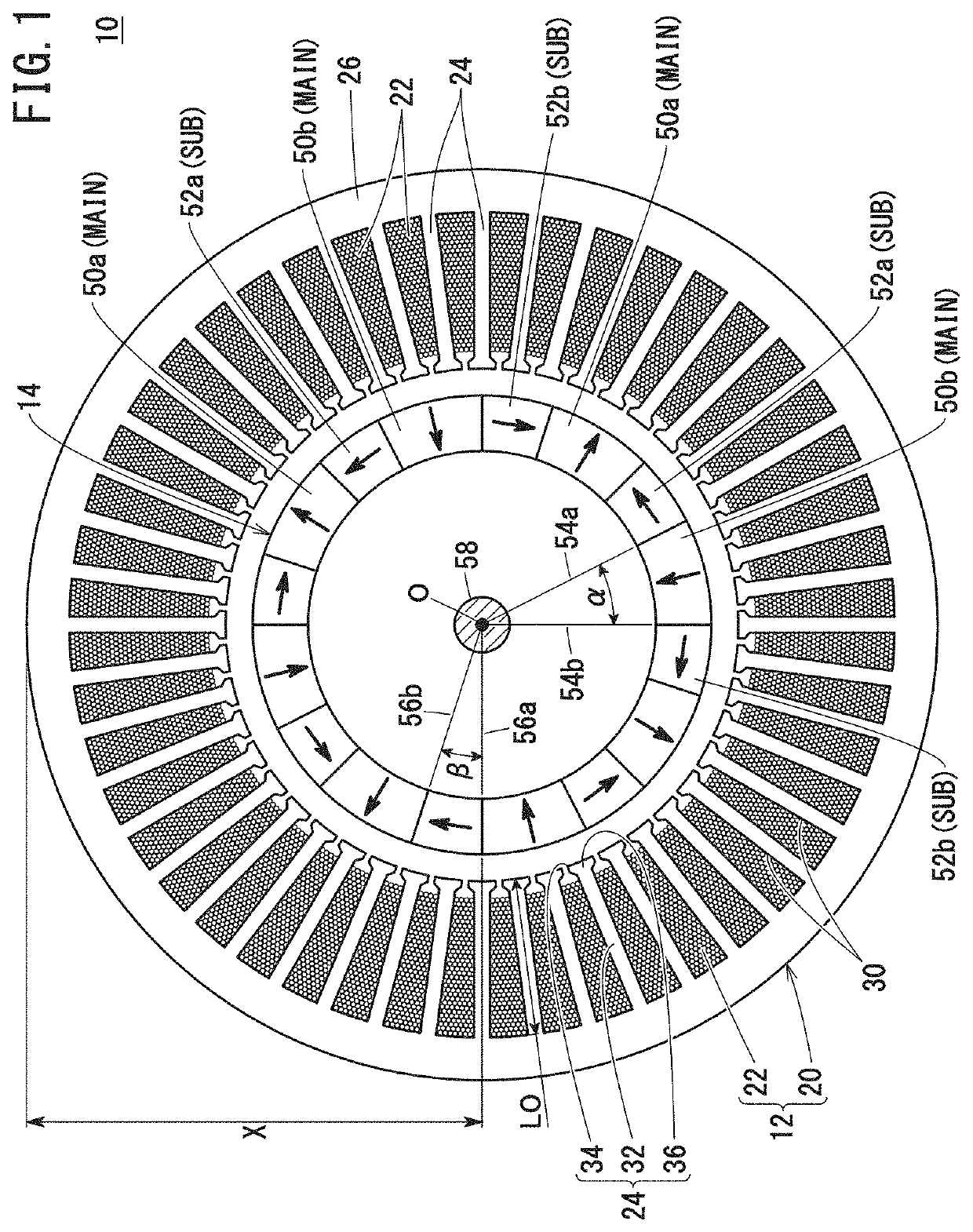
(1) Central Angle α of Main Magnets, Central Angle β of Sub-Magnets

[0074]The average torque was determined by way of simulation, in relation to a rotary electric machine having 8 poles and 48 slots, wherein the central angle α formed by the main magnets differed from each other. For purposes of comparison, the average torque was also calculated for a 48-slot rotary electric machine that was not equipped with sub-magnets and in which eight main magnets were arranged only along the circumferential direction (i.e., a Halbach array was not formed). The results are shown in FIG. 4 as a graph in which the central angles α of the main magnets are depicted on the horizontal axis, and the rate of torque improvement is depicted on the vertical axis, with α=45° serving as a reference (0%). It should be noted that α=45° indicates a situation in which the rotary electric machine is equipped with only eight main magnets. More specifically, in this case, the central angle α of the main magnets is ...

exemplary embodiment 2

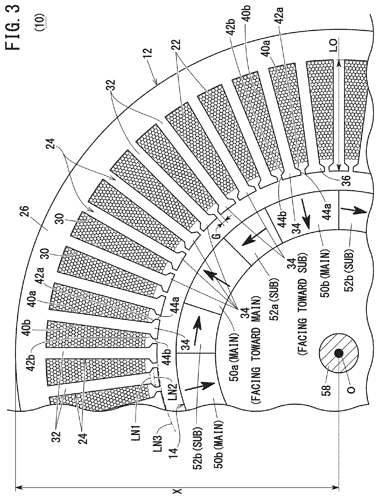
(2) Average Number of Base Portions Facing Toward Main Magnets and Sub-Magnets

[0078]As noted previously, the number of the slots 30 is set to be a multiple of three. On the other hand, the number of poles is a multiple of two, and typically, is an even number between 2 and 12. In FIGS. 5 to 7, there is collectively shown a chart in which the number of the base portions 32 facing toward one of the main magnets and one of the sub-magnets are indicated when the central angles α and β are variously changed under such conditions. The portions of the chart surrounded by the thick frames indicate ranges in which the ratio S14:S23 satisfies the above formula (A).

[0079]From FIGS. 5 to 7, it can be understood that, when S14:S23 lies within a range of 1:1 to 1:0.2, the minimum numbers of the base portions 32 facing toward one of the main magnets and one of the sub-magnet are 1.5 and 0.5, respectively. Further, the maximum numbers of the base portions 32 facing toward one of the main magnets an...

exemplary embodiment 3

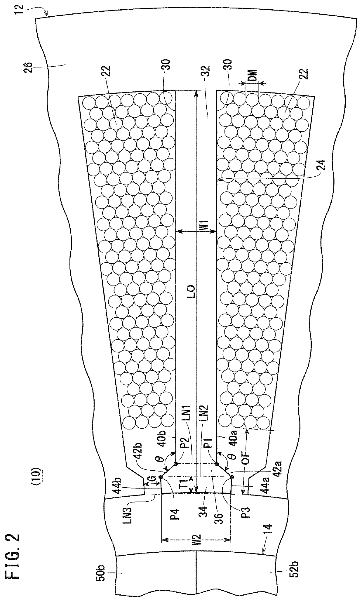
(3) Angle of Intersection θ Between First Parallel Side 40a and First Inclined Side 42a (Second Parallel Side 40b and Second Inclined Side 42b)

[0081]In an 8-pole 48-slot rotary electric machine, the specific iron loss and the specific copper loss when the angle of intersection θ shown in FIG. 2 was changed in various ways were obtained by way of simulation. The respective results thereof are shown as graphs in FIGS. 8 and 9. In this instance, with a time when the angle of intersection θ is 105° being used as a reference, the specific iron loss and the specific copper loss are shown as percentages of the amounts by which they are raised or lowered. When the percentage is positive, it signifies a rising situation, whereas when the percentage is negative, it signifies a falling situation.

[0082]From FIGS. 8 and 9, it can be understood that the larger the angle of intersection θ becomes, the iron loss becomes larger, whereas the copper loss becomes smaller. The respective plot points of ...


PUM


Abstract

A rotor of a rotary electric machine includes a first magnet and a fourth magnet whose magnetic fields are oriented in radial directions of a stator, and a second magnet and a third magnet whose magnetic fields are oriented in circumferential directions of the stator. In the stator, slots are formed between adjacent ones of teeth portions. An electromagnetic coil is provided in the slots. A distal end on an inner circumferential side of the electromagnetic coil is offset from an inner circumferential side end part of a base portion, which is a part of the teeth portion, toward a yoke portion.

Description

CROSS-REFERENCE TO RELATED APPLICATION[0001]This application is based upon and claims the benefit of priority from Japanese Patent Application No. 2020-163300 filed on Sep. 29, 2020, the contents of which are incorporated herein by reference.BACKGROUND OF THE INVENTIONField of the Invention[0002]The present invention relates to a rotary electric machine equipped with a stator including an electromagnetic coil, and a rotor including permanent magnets.Description of the Related Art[0003]As is well known, a rotary electric machine is equipped with a stator that is positioned and fixed, and a rotor that rotates relatively with respect to the stator. An electromagnetic coil is provided in slots that are formed in the stator, in a manner so as to straddle over respective teeth portions. On the other hand, permanent magnets are retained on the rotor. In a motor, accompanying energization or supply of current to the electromagnetic coil, the electromagnetic coil is brought into a magnetic s...

Claims


Application Information

Patent Timeline
IPC IPC(8): H02K1/27H02K1/16H02K3/12
CPCH02K1/2706H02K3/12H02K1/16H02K1/2783H02K2213/03
Inventor YAZAKI, MANABUTAJIMA, SHIGERUABE, SHOEIKUBOTA, YOSHIHISAYAEGAKI, SHO
Owner HONDA MOTOR CO LTD
Why Eureka
Try Eureka