Reduced door opening force and enhanced security flight deck door mechanism

a technology for flight deck doors and operating mechanisms, applied in aircraft accessories, building locks, construction, etc., can solve the problems of significantly more difficult to force open doors, and achieve the effects of reducing door opening force, reducing taper, and reducing the degree of taper

Inactive Publication Date: 2006-04-13
THE BOEING CO
View PDF19 Cites 3 Cited by
  • Summary
  • Abstract
  • Description
  • Claims
  • Application Information

AI Technical Summary

Benefits of technology

[0007] An apparatus to reduce door opening force for an enhanced security flight deck door provides several advantages. A bulbous shaped end of a latch bolt effectively provides a point of contact along an added flat face of a catch arm which multiplies the force as the catch arm rotates. A flattened face of the catch arm provides a smooth contact surface for the bulbous end as the door opens. A solenoid holds a latch pin in an extended solenoid energized position to normally keep the door in a closed, controlled position. By reducing a degree of taper provided at an end of the latch pin below the commonly used taper of approximately 4 degrees, significantly greater force must be applied to the door to force the catch arm to displace the latch pin. Due to both the addition of the bulbous end on the latch bolt and the addition of the flat face to the catch arm the door is therefore easier to open when the solenoid is de-energized and the latch pin is in the de-energized position. The door is significantly more difficult to force open when the latch pin is in the solenoid energized position due to the decreased latch pin taper angle.

Problems solved by technology

The door is significantly more difficult to force open when the latch pin is in the solenoid energized position due to the decreased latch pin taper angle.

Method used


Image

  • Reduced door opening force and enhanced security flight deck door mechanism
  • Reduced door opening force and enhanced security flight deck door mechanism
  • Reduced door opening force and enhanced security flight deck door mechanism

Examples


Embodiment Construction

[0017] The following description of the preferred embodiments is merely exemplary in nature and is in no way intended to limit the invention, its application, or uses.

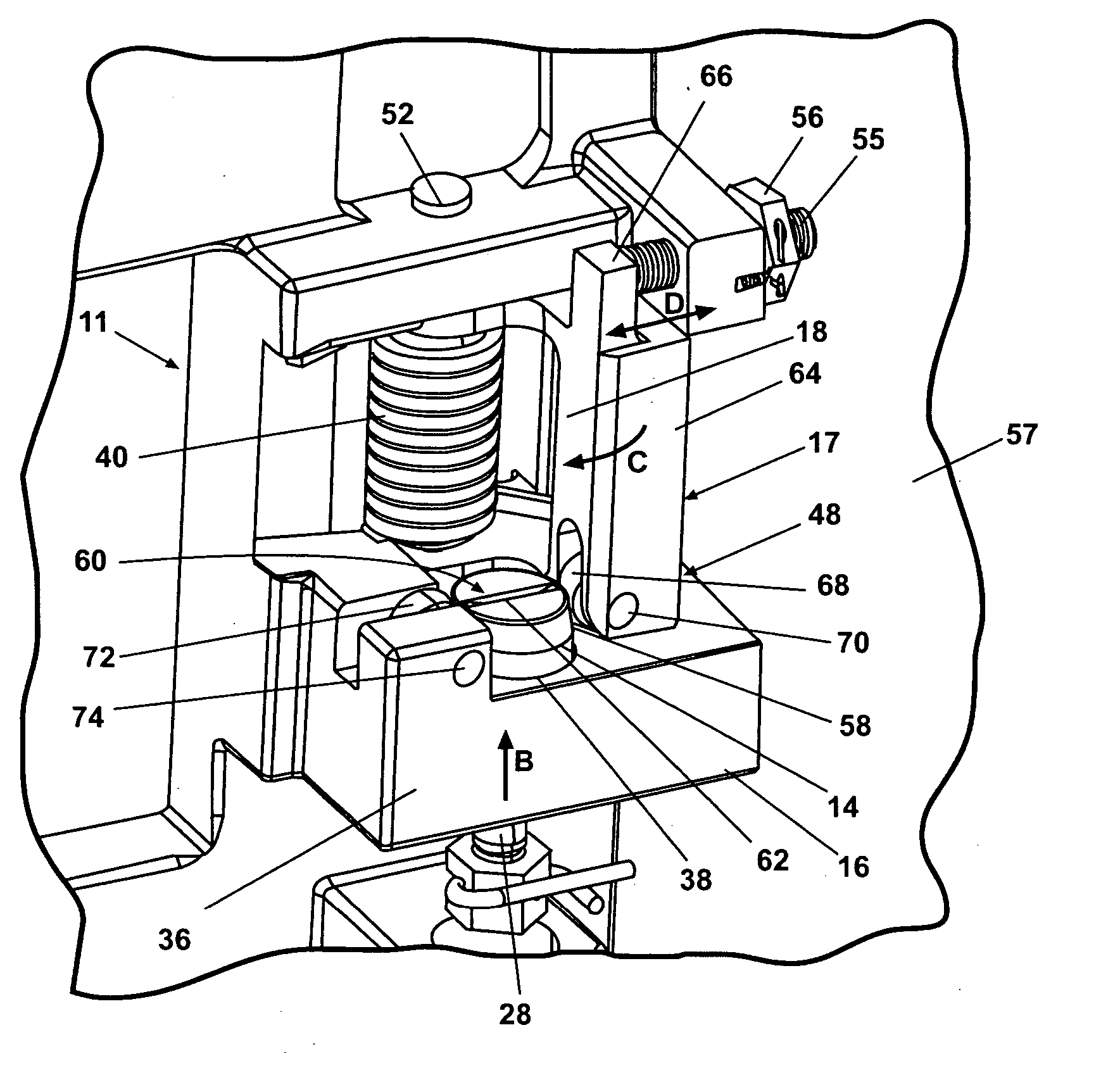
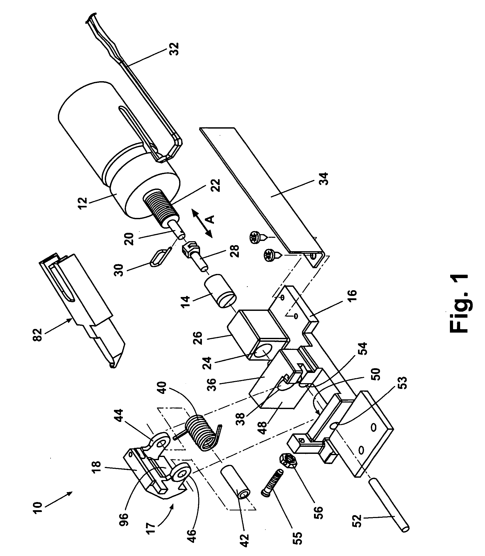
[0018] According to a preferred embodiment of the present invention and referring generally to FIG. 1, a door locking mechanism 10 includes a solenoid 12 which is operable to longitudinally displace a latch pin 14. Latch pin 14 is positioned in slidable engagement with a catch support assembly 16 of the present invention. Solenoid 12 positions latch pin 14 in either of pin displacement direction arrows “A”. A catch arm assembly 17 is rotatably mounted to catch support assembly 16. Latch pin 14 is operable to prevent rotation of a catch arm 18 of catch arm assembly 17 when latch pin 14 is positioned by solenoid 12 in a solenoid energized position of solenoid 12.

[0019] Solenoid 12 further includes a solenoid shaft 20 longitudinally displaceable in the direction of pin displacement direction arrows “A”. Solenoid shaft 2...


PUM


Abstract

An aircraft door mechanism includes a solenoid connected to a support assembly. The solenoid displaces the latch pin between a solenoid energized and a solenoid de-energized position. A catch assembly rotatably connected to the support assembly is positioned to engage a 3-½ degree or less taper portion of the latch pin in the solenoid energized position. When the latch pin moves to the solenoid de-energized position, a latch bolt supported by the door rotates the catch assembly. The latch bolt includes a distal bulbous end which multiplies the force applied to the door to rotate the catch assembly. If the latch pin is extended, a substantially greater force is required to force the latch pin to the solenoid de-energized position owing to the reduced taper of the latch pin. Authorized door entry is therefore easier and unauthorized door entry is made more difficult.

Description

FIELD OF THE INVENTION [0001] The present invention relates in general to door operating mechanisms and more specifically to an electronically locking cockpit door operating mechanism. BACKGROUND OF THE INVENTION [0002] Effectively controlling access to the flight deck or cockpit of a passenger aircraft helps to control numerous risks associated with unauthorized cockpit entry. Typically, aircraft personnel have controlled access to the cockpit through an electronic locking mechanism disposed on or in the cockpit door and / or door frame / structure. Electronic locking systems typically involve solenoid systems having an electric solenoid, a control switch within the flight deck and a keypad for entering an access code. The solenoid when powered automatically engages to lock the door upon closing the door and retracts upon an authorized crew member requesting entry to the flight deck, and the pilots granting access to the flight deck via the control switch or by entering an access code ...

Claims


Application Information

Patent Timeline
Patent Type & Authority Applications(United States)
IPC IPC(8): B64C1/14
CPCB64C1/1469B64C2001/009E05B47/0046E05B47/0004
Inventor KUNDA, JAMES J.KUPFER, SHANNON J.RENZELMANN, MICHAEL E.
Owner THE BOEING CO
Why Eureka
Try Eureka