Optical image stabilizer for camera lens assembly

a technology of optical image stabilizer and camera lens, which is applied in the field of camera devices, can solve the problems of ccd sensors that require high-power consumption and complicated structures, hinder the downsizing and lightening of portable terminals, and often capture unstable images, etc., to achieve low driving resistance, facilitate downsizing and lightening of camera lens assemblies, and prevent unwanted rotation of lenses or image sensors.

Inactive Publication Date: 2006-04-20
SAMSUNG ELECTRONICS CO LTD
View PDF3 Cites 35 Cited by
  • Summary
  • Abstract
  • Description
  • Claims
  • Application Information

AI Technical Summary

Benefits of technology

[0010] The present invention relates to an optical image stabilizer for a camera lens assembly, which facilitates downsizing and lightening of the camera lens assembly.
[0011] One aspect of the present invention is to provide an optical image stabilizer used in a camera lens assembly that is capable of providing a low driving resistance when a lens or image sensor is driven and preventing unwanted rotation of a lens or image sensor.
[0012] Another aspect of the present invention is to provide an optical image stabilizer including: a board having an image sensor on one surface thereof; a double actuator disposed at one side of the board for moving the board in a first direction and a second direction perpendicular to the first direction on a plane; and a guide means for guiding the movements of the board in the first and the second directions, while preventing the board from rotating around an optical axis of the camera lens assembly.

Problems solved by technology

However, the CCD sensors have the drawback of requiring high-power consumption and complicated structures.
When users take photographs with conventional cameras for photographing static images and moving images using the above-mentioned image sensors, unstable images are frequently captured due to shaking cameras resulting from external causes, such as the user's trembling hands or the mounting of cameras on vehicles.
However, the conventional optical image stabilizers hinder the portable terminals from being downsized and lightened.

Method used


Image

  • Optical image stabilizer for camera lens assembly
  • Optical image stabilizer for camera lens assembly
  • Optical image stabilizer for camera lens assembly

Examples


Embodiment Construction

[0017] Hereinafter, embodiments of the present invention will be described with reference to the accompanying drawings. For the purposes of clarity and simplicity, a detailed description of known functions and configurations incorporated herein will be omitted as it may make the subject matter of the present invention unclear.

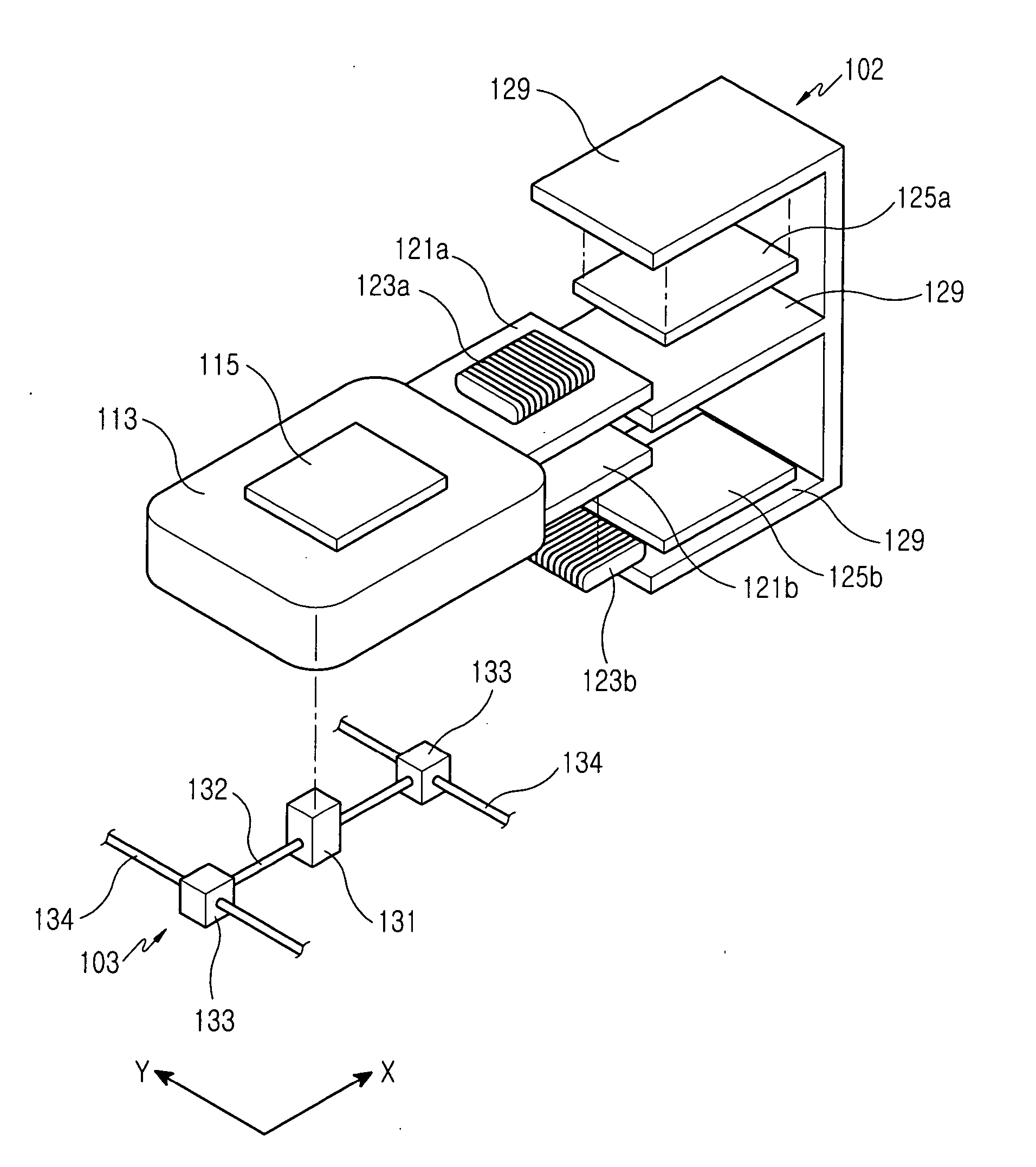
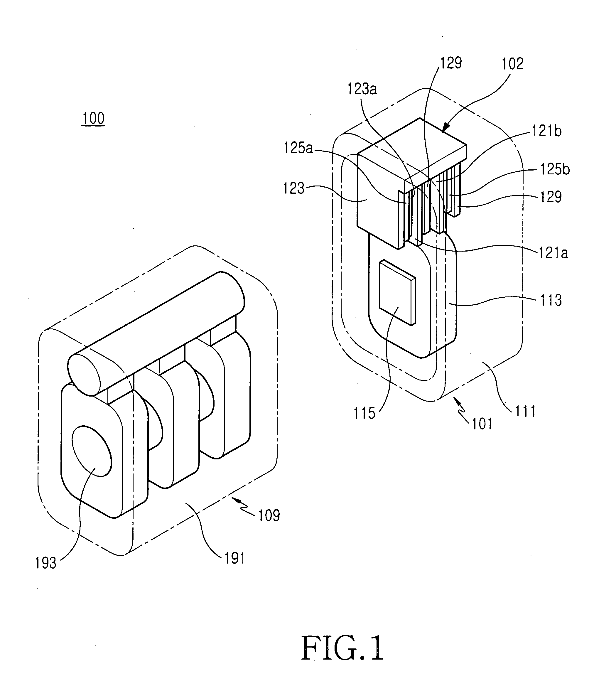
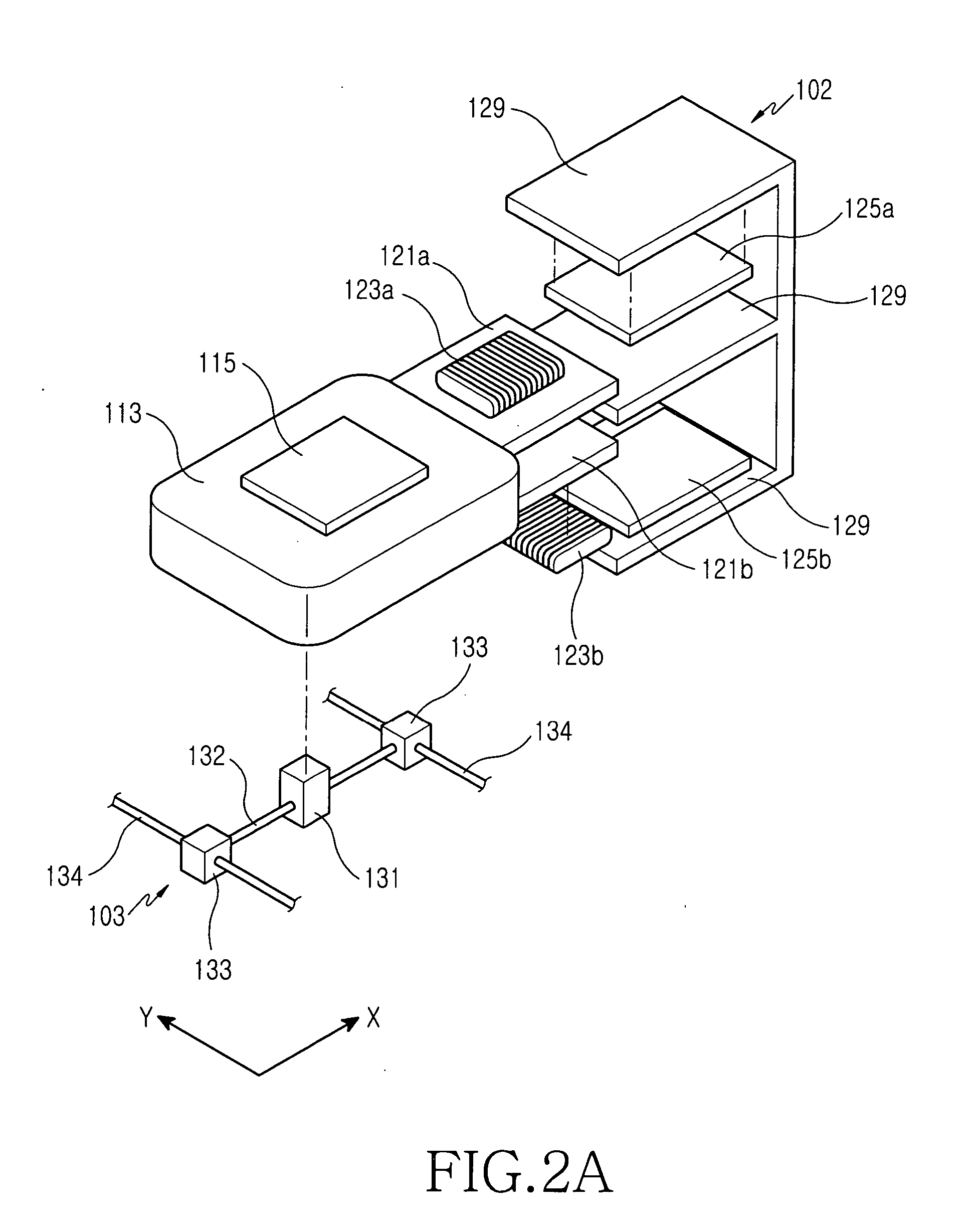
[0018] Referring to FIGS. 1 to 3, an optical image stabilizer according to an embodiment of the present invention includes a board 113, a double actuator 102 and a guide means 103. The optical image stabilizer is disposed in a module housing 111 to form a single sensor assembly 101.

[0019] The sensor assembly 101 forms a camera lens assembly 100 together with a lens assembly 109 including an optical tube structure 191 in which at least one lens 193 is disposed.

[0020] The board 113 has an image sensor 115 on one surface thereof and moves in the module housing 111 by the driving force of the double actuator 102, wherein the movements of the board 113 are guided...


PUM


Abstract

An optical image stabilizer for a camera lens assembly is disclosed and includes: a board having an image sensor on one surface thereof; a double actuator disposed at one side of the board for moving the board in a first direction and a second direction perpendicular to the first direction on a plane; and a guide means for guiding the movements of the board in the first and the second directions, while preventing the board from rotating about an optical axis of the camera lens assembly. The double actuator for moving the board in two directions is disposed at only one side of the board, so that the camera lens assembly including the optical image stabilizer can be downsized. Further, the guide means permits the board to move only linearly in the first direction and the second direction, thereby preventing the image sensor from rotating around an optical axis and thus improving the reliability of the camera lens assembly.

Description

CLAIM OF PRIORITY [0001] This application claims priority to an application entitled “Optical Image Stabilizer for Camera Lens Assembly,” filed in the Korean Intellectual Property Office on Oct. 20, 2004 and assigned Serial No. 2004-83900, the contents of which are hereby incorporated by reference. BACKGROUND OF THE INVENTION [0002] 1. Field of the Invention [0003] The present invention relates to a camera device and, more particularly, to an optical image stabilizer used in a camera lens assembly. [0004] 2. Description of the Related Art [0005] Currently, there are two types of two-dimensional sensors available: a CCD (Chare Coupled Device) sensor and a CMOS (Complementary Metal Oxide Semiconductor) sensor. These sensors are used in cameras for photographing dynamic and static images. The CCD sensors are superior to the CMOS sensors in image quality. However, the CCD sensors have the drawback of requiring high-power consumption and complicated structures. As a result, the demand fo...

Claims


Application Information

Patent Timeline
Patent Type & Authority Applications(United States)
IPC IPC(8): H04N5/228
CPCG02B27/646H04N5/2254H04N5/23248H04N5/23287H04N23/55H04N23/68H04N23/687H04N23/60
Inventor KOO, JUN-MO
Owner SAMSUNG ELECTRONICS CO LTD
Why Eureka
Try Eureka