Apparatus of LED flat light signal display

Active Publication Date: 2006-04-20
IND TECH RES INST
View PDF5 Cites 20 Cited by
  • Summary
  • Abstract
  • Description
  • Claims
  • Application Information

AI Technical Summary

Benefits of technology

[0013] It is the secondary objective of the invention to provide an apparatus of LED flat light signal display, capable of tightly arranging the light spots reshaped by the cooperation of a plurality of flat microlens and a microlens array arranged therein and thus forming a flat geometric light-emitting source for displaying information smoothly.
[0015] To achieve the foregoing objectives, the present invention provides an apparatus of LED flat light signal display, comprising at least a light emitting diode (LED), a plurality of flat microlens and at least a microlens set. The light emitting diode acts as a light source for emitting light. The flat microlens comprises a plurality of concentric serrated rings for performing the collimating and converging light received from the LED. The microlens set comprises at least one microlens unit with a specific geometric shape, each micro unit being capable of receiving the light emitted from the flat microlens to produce a light spot identical to the specific geometric shape, and the micro unit at its external edge has a lateral side to be disposed next to a lateral side of another micro unit, such that a geometric plane is defined by the totality of the plural micro units. The present invention can provide a maximum viewing area with a minimum quantity of LEDs while being applied in a dot matrix LED signal or an imaging device, and also can make the images produced by the device smoother to enhance the comfort of viewing.

Problems solved by technology

However, such arrangement only gives very little effect and is not suitable for large flat panel display.
(2) The LED array used in signal devices, such as the traffic lights, taillights, large outdoor electronic billboards, etc., cannot achieve the smooth display effect under the prior-art structure.
In addition, the LED array is not packaged by flat packaging, which increases the volume of the LED package and thus affects the smoothness of the image and text displayed on the signal device.

Method used


Image

  • Apparatus of LED flat light signal display
  • Apparatus of LED flat light signal display
  • Apparatus of LED flat light signal display

Examples


Embodiment Construction

[0025] For your esteemed members of reviewing committee to further understand and recognize the fulfilled functions and structural characteristics of the invention, several preferable embodiments cooperating with detailed description are presented as the follows.

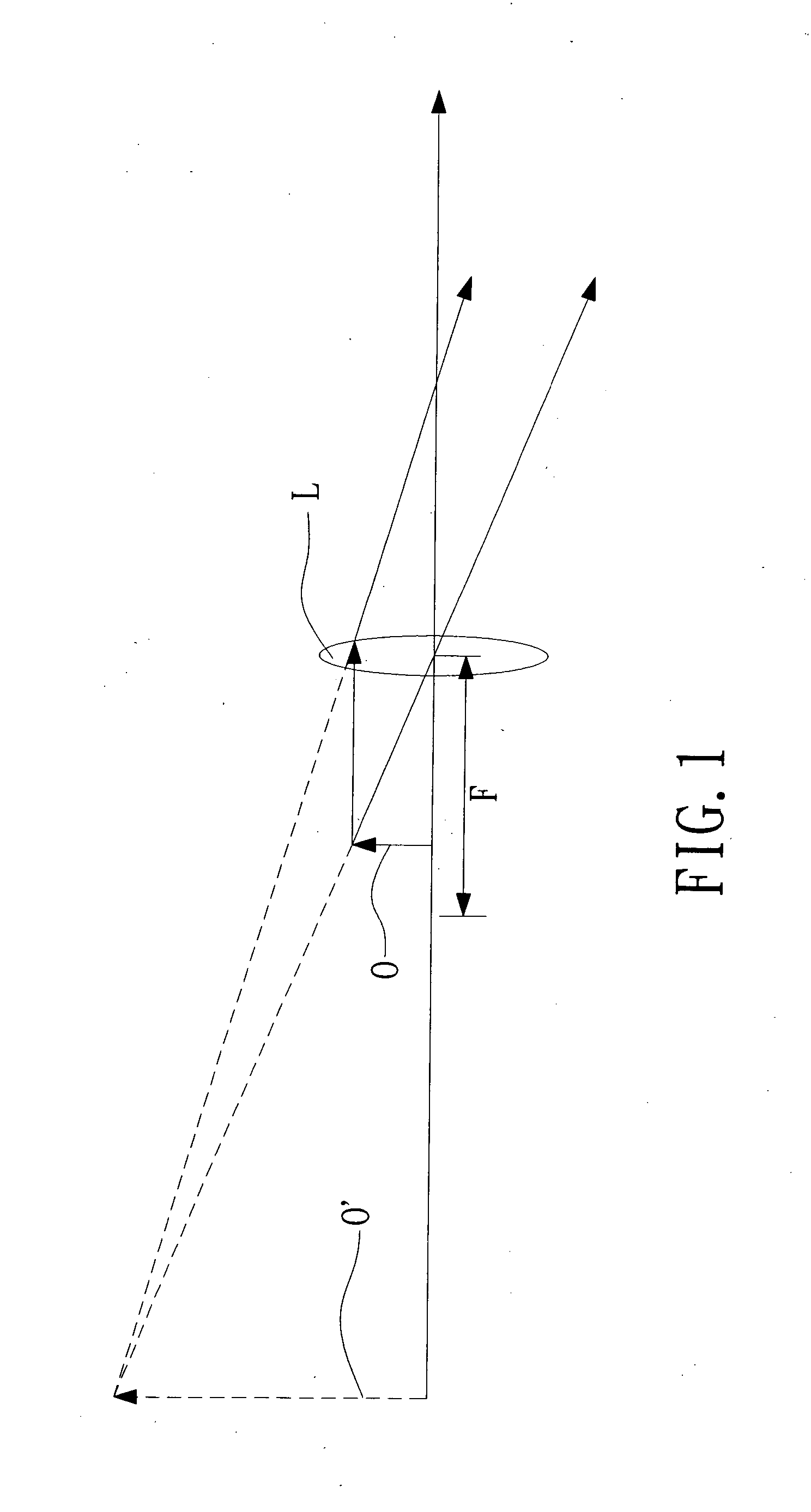
[0026] Please refer to FIG. 1 for the imaging principle of the present invention. If an object O is situated within the focal length F of a lens L, an enlarged virtual image O′ will be produced due to the focusing of virtual rays while viewing the object O from a side of the lens opposite to the object O being situated. That is, if the object O is a light spot and locates within the focal length F of the lens L, the light spot is enlarged and expanded while it is viewed from another side of the lens.

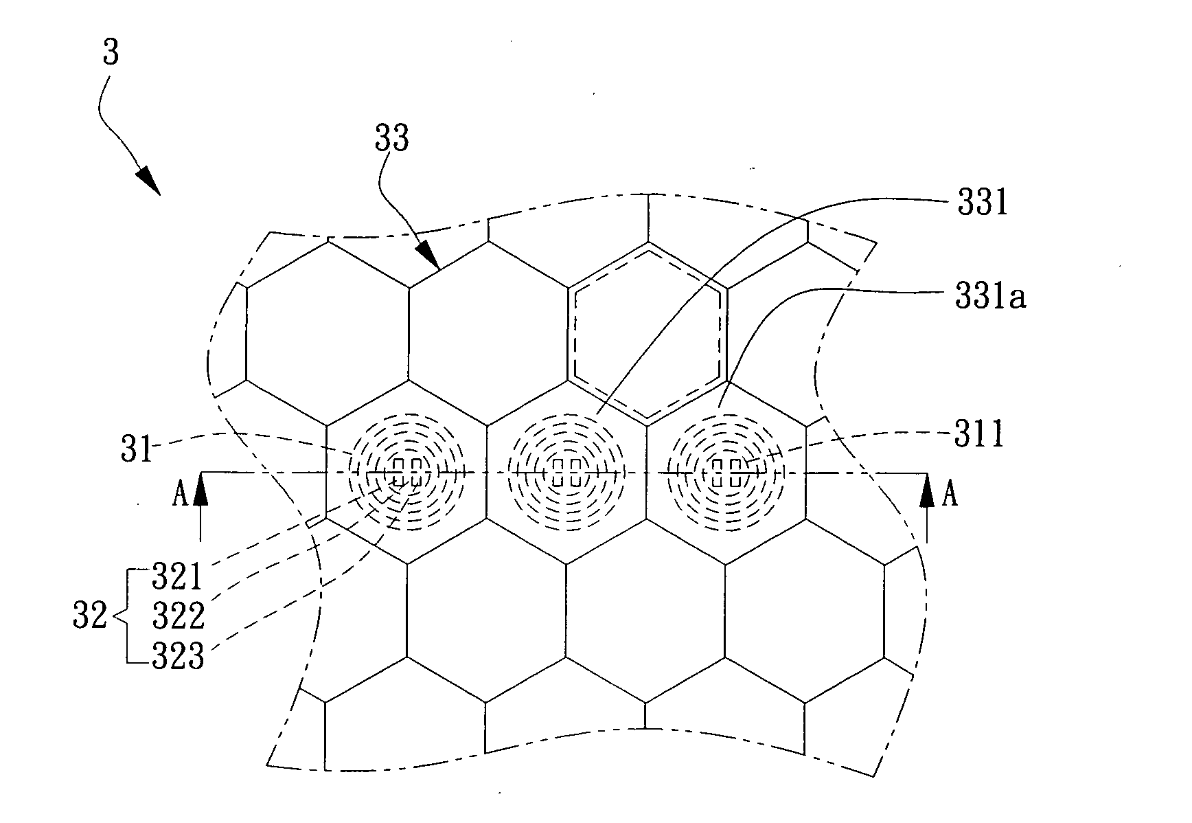
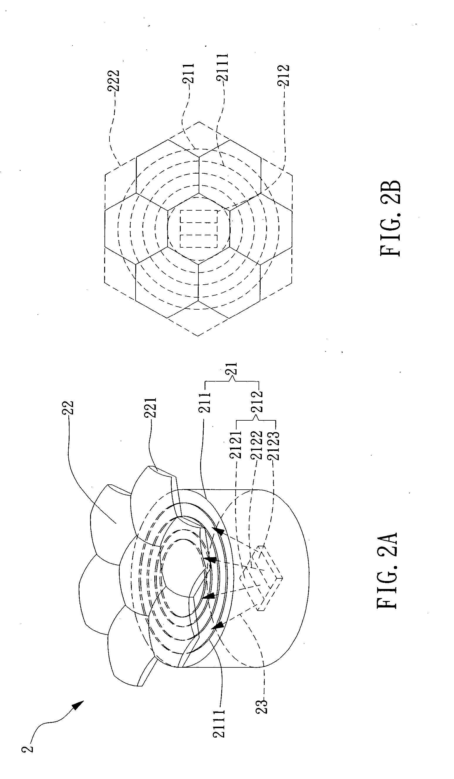
[0027] Please refer to FIG. 2A for the illustrative view of the LED display device according to a preferred embodiment of the present invention. The LED display device 2 comprises a lens light source section 21 and a microlens ...


PUM


Abstract

The present invention discloses an apparatus of LED flat light signal display, which comprises at least one light emitting diode, a plurality of flat microlens and at least one microlens set. The light emitting diode acts as a light source for discharging light. The flat microlens comprises a plurality of concentric serrated rings for collimating and converging convergence received from the light source. The microlens set comprises at least one microlens unit with a specific geometric shape for receiving light transmitted from the flat microlens to produce a light spot identical to the specific geometric shape, and the micro unit has a lateral side on its external edge to be disposed next to another lateral side of another micro unit to define a geometric plane. The present invention can provide a maximum viewing area with a minimum quantity of LEDs while being applied in dot matrix LED signals or imaging devices, and also make the images produced by the device smoother to enhance the comfort of viewing.

Description

1. FIELD OF THE INVENTION [0001] The present invention relates to an apparatus of LED flat light signal display, and more particularly, to a high efficiency direct view LED signal display apparatus incorporating a flat microlens and a microlens array. 2. BACKGROUND OF THE INVENTION [0002] At present, light emitting diodes (LEDs) are commonly used in televisions, PC display devices, digital cameras, mobile phones, lamps, various sized billboards, traffic lights, and automobile warning lamps, etc. In recent years, the LED industry in Taiwan grows rapidly and has become the world's second largest supplier, just second to Japan. Therefore, the LED industry is considered as a blooming industry with a large business opportunity that is going to succeed the flat panel industry. [0003] The Taiwan's LED industry shows a high growth in recent years and is expected to have a total annual output value of 25.3 billion NT dollars and a global market share of 21% (only second to Japan's 47%) by 20...

Claims


Application Information

Patent Timeline
IPC IPC(8): G02B27/10G02B3/00G02B27/00G02B27/09G09F9/30
CPCG02B3/0031G02B3/0043G02B3/0056G02B3/0062G09F9/33G02B19/0066G02B19/0014
Inventor PO-HUNG, YAOYU-NAN, PAOYI-TING, SUNMING-FONG, CHEN
Owner IND TECH RES INST
Why Eureka
Try Eureka