
Motorized stapler

Active Publication Date: 2006-04-27
MAX CO LTD
View PDF16 Cites 2 Cited by
  • Summary
  • Abstract
  • Description
  • Claims
  • Application Information

AI Technical Summary

Benefits of technology

[0007] It is an object of the invention to solve the problem in the related art and to provide an electric stapler capable of shortening one-cycle operating time required for each staple binding performed by respective drive motors provided on a clincher unit and a driver unit.

Problems solved by technology

By the way, while according to the related art, at a point of time when clamp by the clincher unit is terminated, the drive motor m1 of the driver unit is driven to perform striking simultaneously when the drive motor m2 of the clincher unit is stopped, and at a point of time when striking is terminated, the drive motor m1 of the driver unit is stopped and the drive motor m2 of the clincher unit is again driven to actuate the clincher mechanism, there is caused a problem that starting generally takes time at the beginning of driving of a motor until the motor reaches a predetermined rotational speed, and a primary operation is not performed during the starting time, so that the necessary time in one cycle of staple binding is lengthened by periods L1, L2, L3 of starting time.

Method used


Image

  • Motorized stapler
  • Motorized stapler
  • Motorized stapler

Examples


Embodiment Construction

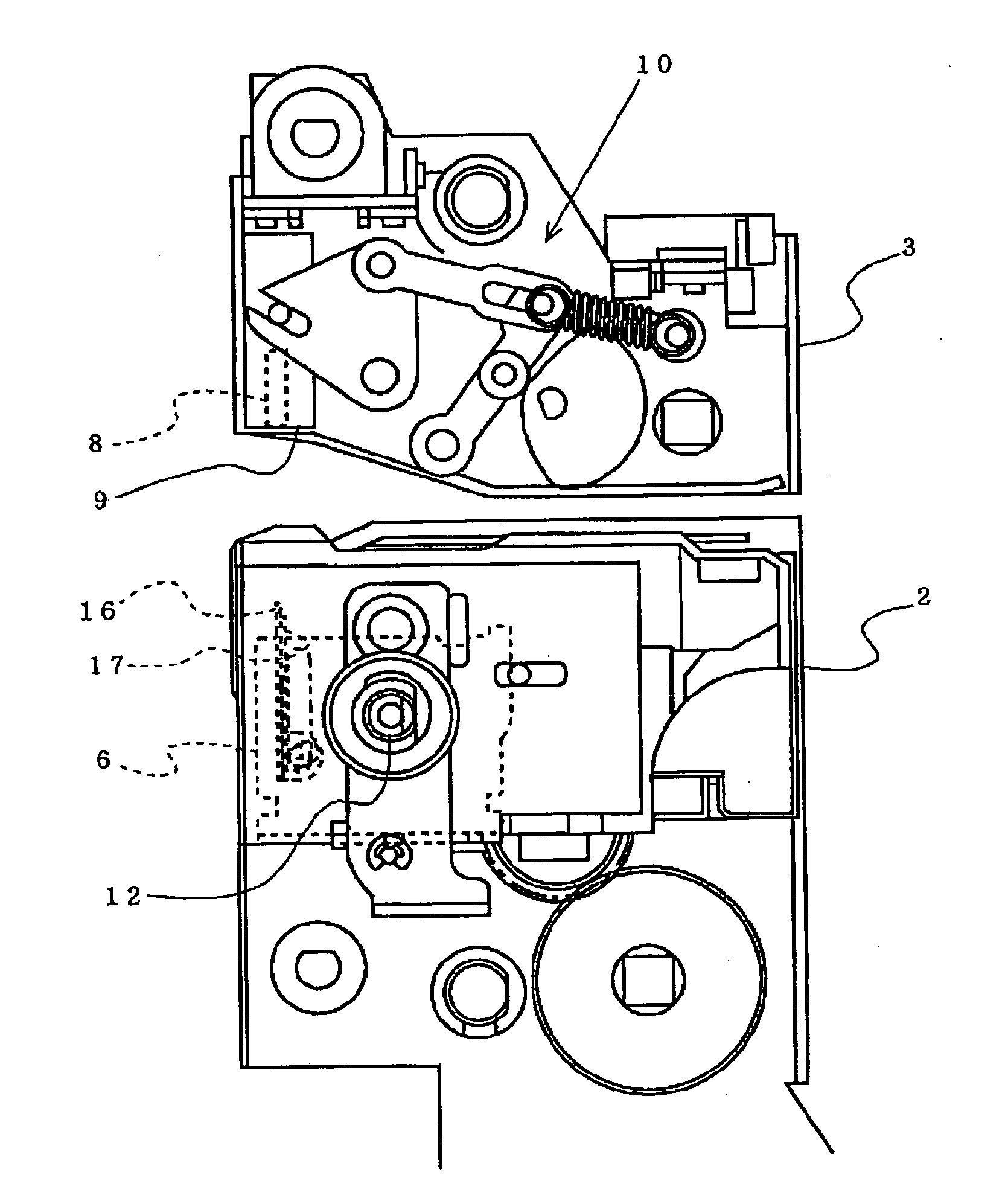
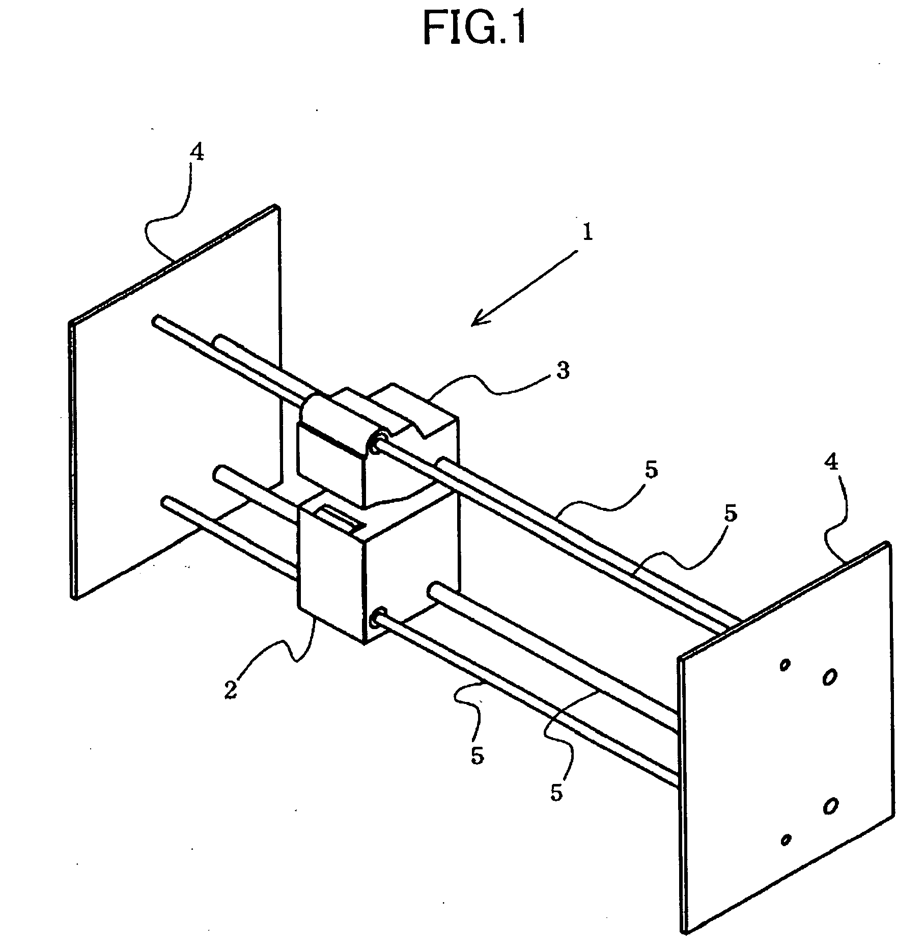
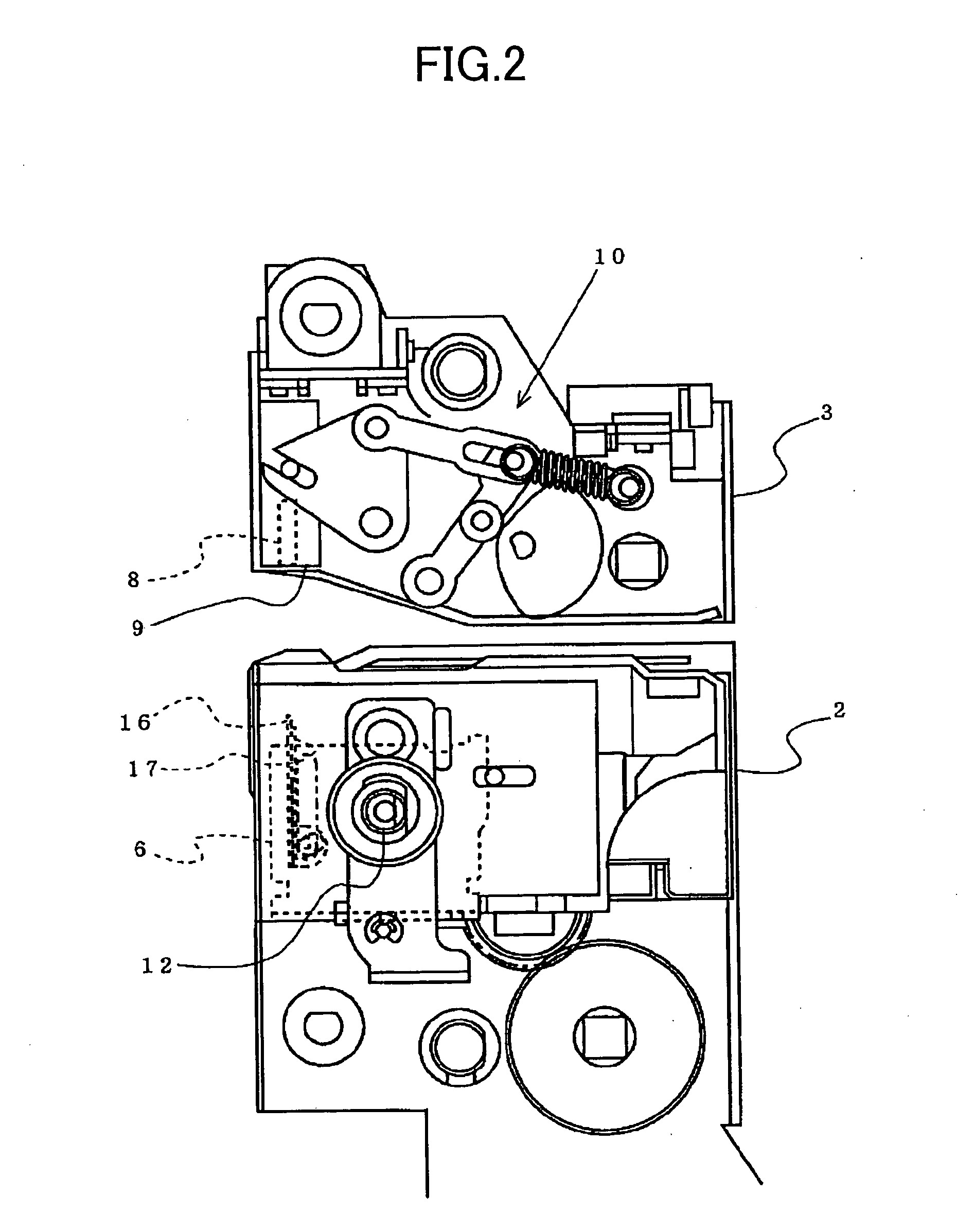
[0023] A mode for carrying out an electric stapler according to the invention will be described by way of an embodiment shown in the drawings. An electric stapler 1 is accommodated inside, for example, a copying machine, a printing machine, or the like to be provided midway a conveyance path, along which copied or printed sheets to be bound are conveyed, and comprises a driver unit 2 arranged on a lower surface side of the conveyance path and a clincher unit 3 arranged on an upper surface side of the conveyance path, as shown in FIG. 1. The driver unit 2 and the clincher unit 3 interpose therebetween the conveyance path of the sheets to be vertically separated from each other, are arranged in a state of being spaced away from each other so as to enable the sheets to pass between the both units 2, 3, and are supported so as to be able to move synchronously along guide shafts 5, which are installed between frames 4 arranged on both sides of the conveyance path, in a direction perpendi...


PUM


Abstract

A driver unit 2 for striking out of a staple, and a clincher unit 3 for clinch of legs of a staple are separated vertically from each other, the driver unit 2 and the clincher unit 3, respectively, are provided with drive motors M1, M2, encoders 21, 40 are formed on respective drive shafts 12, 30, which drive the driver unit 2 and the clincher unit 3, to generate pulse signals P1, P2 upon rotation of the respective drive shafts, a control device 47 inputs thereinto the pulse signals P1, P2 to count the same, and the respective drive motors M1, M2 are controlled by the control device 47 on the basis of count values.

Description

TECHNICAL FIELD [0001] The present invention relates to an electric stapler, in which a driver unit for striking out of a staple and a clincher unit for bending legs of a staple are vertically separated from each other, drive motors are mounted on the respective units, and the respective drive motors drive a driver and a clincher mechanism. BACKGROUND ART [0002] Electric staplers accommodated inside, for example, a copying machine, a printing machine, or the like to bind a plurality of copied or printed sheets to be bound have been conventionally known. In such electric staplers, a driver unit for striking out of a staple toward sheets, and a clincher unit for bending legs of a staple penetrated through sheets are vertically separated from each other and arranged to be spaced from each other, whereby sheets can pass between the respective units. In such electric staplers, after sheets are arranged between the respective units, the clincher unit is lowered toward sheets, as arranged ...

Claims


Application Information

Patent Timeline
IPC IPC(8): B25C7/00B27F7/00B27F7/19
CPCB27F7/006B27F7/19
Inventor KOBAYASHI, HISASHI
Owner MAX CO LTD
Features
  • Generate Ideas
  • Intellectual Property
  • Life Sciences
  • Materials
  • Tech Scout
  • Unparalleled Data Quality
  • Higher Quality Content
  • 60% Fewer Hallucinations
Learn More