Optical-acoustic imaging device

a technology of optical acoustic imaging and imaging device, which is applied in the direction of instruments, catheters, applications, etc., can solve the problems of a limited image area, a risk to the patient of arterial spasm, and the external diameter of conventional mechanical and solid-state ivus catheters, so as to reduce radiation exposure and shorten the total procedure time

Inactive Publication Date: 2008-05-22
PHYZHON HEALTH INC
View PDF39 Cites 146 Cited by
  • Summary
  • Abstract
  • Description
  • Claims
  • Application Information

AI Technical Summary

Benefits of technology

[0011] The present invention is a guidewire imaging device for vascular or non-vascular imaging utilizing optico-acoustical methods, which device has a profile of less than 1 mm in diameter, and most preferably less than 0.5 mm in diameter. The imaging device of the invention comprises a single-mode optical fiber with at least one Bragg grating and a piezoelectric or piezoceramic jacket, which device may achieve omnidirectional (360°) imaging. The imaging guidewire of the invention can function as the guidewire for vascular interventions, and can enables real time imaging during balloon inflation and stent deployment, thus will provide clinical information that is not available when catheter-based imaging systems are used. The device of the invention may enable shortened total procedure times, including the fluoroscopy time, and will also reduce radiation exposure to the patient and the operator.

Problems solved by technology

The design of these devices generally creates difficulties in tracking with a limited image area, and vibration of the catheter during rotation poses a risk to the patient of arterial spasm.
One deficiency in conventional mechanical and solid state IVUS catheters is the external diameter, generally approximately 1.2 mm.
Mechanical limitations on component sizes and noise effects have thus far limited commercially feasible manufacture of a smaller diameter device.
However, it is difficult to adapt this technology to small (less than 1.2 mm diameter) imaging catheters with multiple elements, for several reasons.
This relationship of elements in the device generally results in a low signal / noise relation While the signal to noise ration may be increased by the use of preamplifiers near the receivers, physically accommodating the preamplifiers inside of a space with an outer diameter of less than 1.2 mm is very difficult.
These devices are limited, however, in that they generate doppler signals and not images, and their probing range is limited to the area just in front of the catheter pass.
Also, the piezoelectric chip is not small enough to be used in a device with a profile diameter of less than 1 mm, and more importantly, less than 0.5 mm.
In most commercially available piezoceramic and PVDF IVUS devices, one significant problem is the difficulty in constructing ultrasound imaging catheters with a diameter of less then approx.
Such devices are also difficult to manufacture from a mechanical perspective, using conventional components.

Method used


Image

  • Optical-acoustic imaging device
  • Optical-acoustic imaging device
  • Optical-acoustic imaging device

Examples


example 1

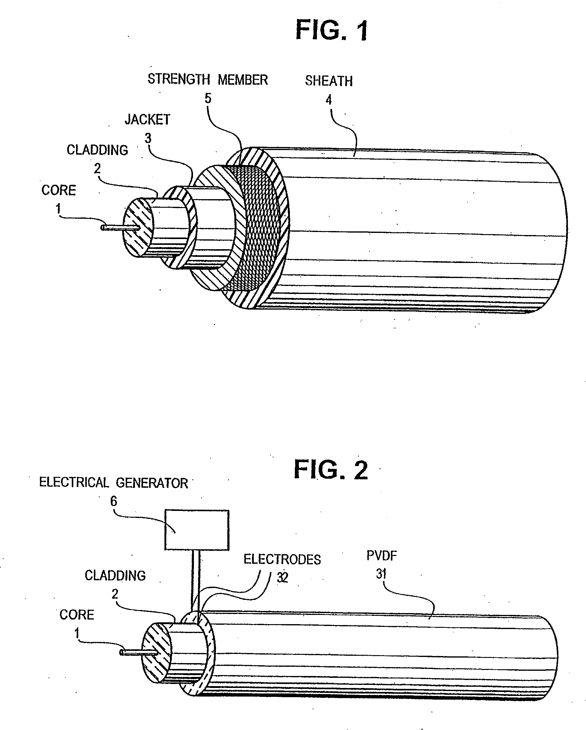
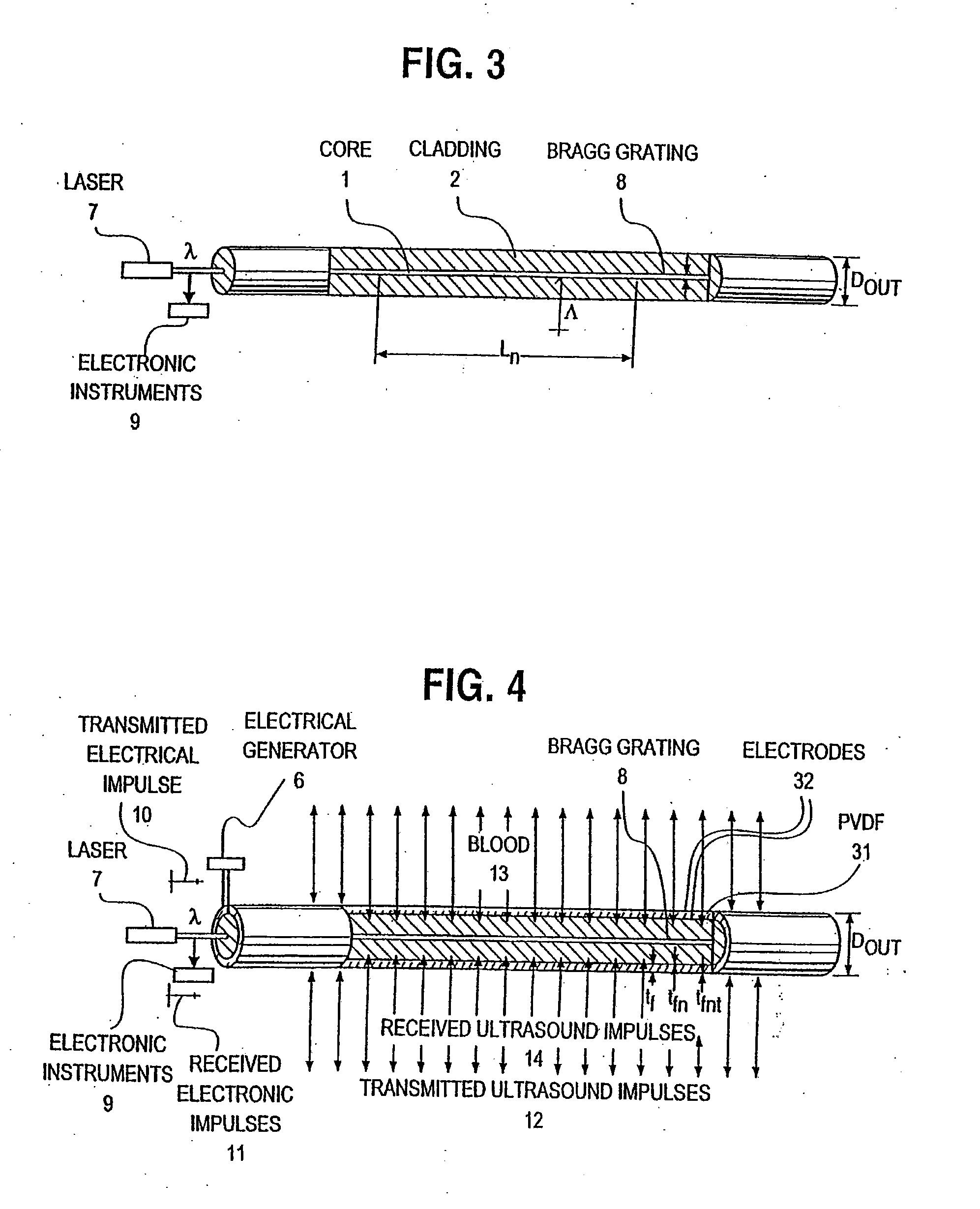
[0034] One preferred embodiment of the invention is illustrated in FIG. 4. This embodiment includes a single-mode optical fiber with a Bragg grating 8 and a piezoelectric or piezoceramic jacket 31. The jacket may be any suitable piezoelectric or piezoceramic material, and one preferable material is poled PVDF. It is contemplated that other jacket materials will work with the invention, so long as the material has suitable flexibility and piezoelectric characteristics.

[0035] In the preferred embodiment of the device of the invention as illustrated in FIG. 4, an electrical generator 6 transmits ultrasound impulses 10 to both the Bragg grating 8 and to the outer medium 13 in which the device is located, for example, the blood. Primary and reflected impulses 11 are received by the Bragg grating 8 and recorded by electronic instruments 9 using conventional methods, such as by a photodetector and an oscilloscope. From the recorded signals, a corresponding image is generated by convention...

example 2

[0038] It may also be possible to expand the frequency band of the signal by using a damped silica fiber. In this variation of the preferred embodiment of the invention, frequency band expansion causes shortening of the signal in time, which improves the resolution of the received signal. For instance, using a damped fiber in a device of the invention, we have obtained maximum widths of the frequency band of the signal of approximately 110, although another variations will be achieved depending upon experimental conditions. If damped fibers are utilized, transmitters transmitting at less than 40 MHz may be used.

example 3

[0039] As shown in FIG. 5, one other preferred embodiment of an imaging device in accordance with the invention comprises a plurality of Bragg gratings 81 with different periods, each period being approximately 0.5μ. By using multiple Bragg gratings, a set of distributed sonars are obtained. By utilizing a tunable laser 71 as previously described, we obtain scanning over an omnidirectional array. A Bragg grating length LB of some hundreds of optical wavelengths are sufficient to reflect considerable part of the optical beam. The ultrasound impulses 141 are received only by the Bragg gratings 81, with the period of Λ1 which is equal to the aperture Ax.


PUM

PropertyMeasurementUnit
diameteraaaaaaaaaa
diameteraaaaaaaaaa
outer diameteraaaaaaaaaa

Abstract

The present invention is a guide wire imaging device for vascular or non-vascular imaging utilizing optic acoustical methods, which device has a profile of less than 1 mm in diameter. The ultrasound imaging device of the invention comprises a single mode optical fiber with at least one Bragg grating, and a piezoelectric or piezo-ceramic jacket, which device may achieve omnidirectional (360°) imaging. The imaging guide wire of the invention can function as a guide wire for vascular interventions, can enable real time imaging during balloon inflation, and stent deployment, thus will provide clinical information that is not available when catheter-based imaging systems are used. The device of the invention may enable shortened total procedure times, including the fluoroscopy time, will also reduce radiation exposure to the patient and to the operator.

Description

I. RELATED APPLICATIONS [0001] This application is a Continuation of U.S. application Ser. No. 10 / 685,226, filed on Oct. 14, 2003, which is a Continuation of U.S. application Ser. No. 09 / 623,248, filed on Jun. 11, 2002, now issued as U.S. Pat. No. 6,659,957, which is a National Stage filing under 35 U.S.C. 371 of PCT / US99 / 04913, filed on Mar. 5, 1999, published in English as WO 99 / 5059 on Nov. 18, 1999, which claims priority to U.S. Provisional Application No. 60 / 076,862, filed on Mar. 5, 1998, which applications and publications are incorporated herein by reference.II. FIELD OF THE INVENTION [0002] The present invention relates to an omnidirectional imaging device for vascular or nonvascular imaging that may be used as an intravascular guidewire. III. BACKGROUND OF THE INVENTION [0003] Intra-vascular and non-vascular imaging are very important techniques that provide information that is not available by angiographic imaging methods such as information about the composition of the s...

Claims


Application Information

Patent Timeline
Patent Type & Authority Applications(United States)
IPC IPC(8): A61B8/00A61B8/12G01N29/00A61B17/22A61B19/00
CPCA61B5/0097A61B2019/5217A61B2017/22042A61B5/0095G01H9/004A61B8/12A61B2090/3614A61B8/56
Inventor VARDI, GIL M.SPIVAK, VICTOR
Owner PHYZHON HEALTH INC
Why Eureka
Try Eureka